Werbung
Quicklinks
GAMMA instabus
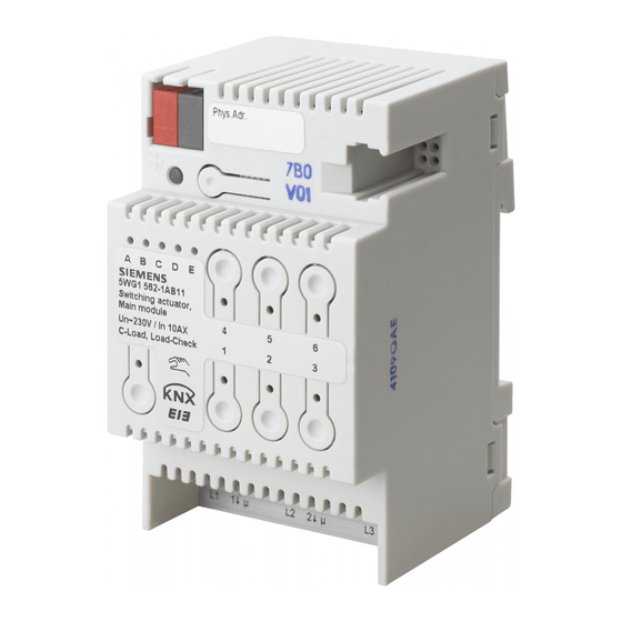
N 562/11 Schaltaktor, Hauptmodul
N 562/11 Switching actuator, main module
3x AC 230/400V, 10A, C-load, load-check
5WG1 562-1AB11
Bedien- und Montageanleitung
Operating and Mounting Instructions
Stand: September 2008
As at: September 2008
Schaltaktor, Hauptmodul
Switching actuator, main module
N 562/11
L1
Ausgang 1
Output 1
1
L2
Ausgang 2
Output 2
2
L3
Ausgang 3
Output 3
3
A
6
Schaltaktor, Erweiterung
Switching actuator, submodule
N 562/21 / N512/21
L1
Ausgang 1
Output 1
1
L2
Ausgang 2
2
Output 2
L3
Ausgang 3
Output 3
3
B
C ... E
Bild / Figure 1
A5E02223695A
DS 01
Produkt- und Funktionsbeschreibung
Das Schaltaktor-Hauptmodul N 562/11 ist ein Reiheneinbauge-
rät im N-Maß. Es kann über seine drei Relaiskontakt-Ausgänge
drei voneinander unabhängige Gruppen elektrischer Verbrau-
cher schalten. Der Busanschluss erfolgt über eine Busklemme,
die Stromversorgung der Aktor-Elektronik über die Busspan-
nung.
An die 6-polige Schnittstelle des Schaltaktor-Hauptmoduls
N 562/11 (siehe Gerät A in Bild 1) kann mit einem speziellen
Brückenstecker eine Schaltaktor-Erweiterung N 562/21 oder
N 512/21 angeschlossen werden (siehe Gerät B in Bild 1). An ei-
ne Schaltaktor-Erweiterung kann ebenfalls eine weitere Schalt-
aktor-Erweiterung angeschlossen werden. Bis zu 4 Schaltaktor-
Erweiterungen N 562/21 oder N 512/21 dürfen an ein Schaltak-
tor-Hauptmodul N 562/11 in Reihe angeschlossen werden, so
dass ein Hauptmodul bei Bedarf einfach erweiterbar ist von ei-
nem 3-fach zu einem 6-fach, 9-fach, 12-fach oder 15-fach
Schalt-aktor und so flexibel an Anzahl und Größe der zu schal-
tenden Lasten anpassbar ist.
Über 5 grüne Leuchtdioden (LED) auf der Oberseite des Haupt-
moduls (siehe Bild 2, A5) wird angezeigt, welches Modul ange-
wählt wurde (LED = EIN). Ein Modul wird angewählt, indem der
Taster „Direktbetrieb" (siehe Bild 2, A6) so lange mehrmals kurz
gedrückt wird, bis die LED des gewünschten Moduls A...E auf-
leuchtet. Blinkt eine der LED A...E, so wurde bei diesem Modul
ein Fehler ermittelt. Dies ist z.B. der Fall, wenn mehr Module
parametriert als tatsächlich angeschlossenen sind oder wenn
der parametrierte Modultyp mit dem tatsächlich angeschlosse-
nen Modul nicht übereinstimmt oder wenn ein Modul als defekt
erkannt wurde.
Über den Taster „Direktbetrieb" (siehe Bild 2, A6) mit integrier-
ter gelber LED kann zwischen „Busbetrieb" und „Direktbetrieb"
umgeschaltet werden. Wird dieser Taster kurz gedrückt, so wird
30 Sekunden lang angezeigt, welches der Module A...E (siehe
Bild 2, A5) zuletzt angewählt wurde und über die in die Taster
1...3 integrierten roten LED (siehe Bild 2, A9), welchen Schalt-
zustand der jeweilige Ausgang aufweist (Kontakt geschlossen:
LED=EIN bzw. Kontakt offen: LED=AUS).
Wird der Taster zum Einschalten des Direktbetriebs dagegen
mindestens 3 s lang gedrückt, so leuchtet die gelbe LED zur An-
zeige des Direktbetriebs dauerhaft auf. Im Direktbetrieb kann
jeder Ausgang des aktuell angewählten Moduls über den zuge-
ordneten Taster auf der Oberseite des Hauptmoduls per UM-
Funktion geschaltet werden: ein erstes Drücken eines Tasters
L3
N
L1
L2
führt, bei ausgeschaltetem Ausgang, zum Einschalten, ein zwei-
tes Drücken zum Ausschalten. Der Schaltzustand des Ausgangs
wird über die in den Taster integrierte rote LED angezeigt. (Hin-
weis: Die Taster 4...6 und die integrierten LED sind beim
N 562/11 ohne Funktion.) Um den Schaltzustand der Ausgänge
eines anderen Moduls zu ändern, muss dieses zuerst angewählt
werden. Hierzu muss der Taster „Direktbetrieb" mehrmals kurz
gedrückt werden, bis die LED des gewünschten Moduls A bis E
aufleuchtet. Module, die nicht als angeschlossen parametriert
sind, sind nicht anwählbar.
Über einen Parameter ist einstellbar, ob der Direktbetrieb dau-
erhaft oder zeitbegrenzt einschaltbar ist. Werkseitig ist der Di-
rektbetrieb auf eine zeitlich begrenzte Einschaltdauer von 15
Minuten eingestellt. Bei jeder Tasterbetätigung im Direktbetrieb
wird das Zeitglied zur Einschaltdauerbegrenzung mit der para-
metrierten Einschaltdauer erneut gestartet. Nach Ablauf der
Einschaltdauer ohne eine weitere Tasterbetätigung wird der Di-
rektbetrieb selbsttätig ausgeschaltet und somit der „Busbetrieb"
wieder aktiviert (sofern eine Kommunikation über den Bus mög-
lich ist). Alternativ kann der Direktbetrieb durch erneutes Drü-
cken des Tasters „Direktbetrieb" für mindestens 3 s jederzeit be-
endet werden. Dann erlischt die gelbe LED zur Anzeige des Di-
rektbetriebs, und der Aktor ist wieder im Busbetrieb. Im Busbe-
trieb ist ein Betätigen der Taster zum direkten Ein- bzw. Aus-
schalten eines Ausgangs wirkungslos. Bei eingeschaltetem Di-
rektbetrieb über den Bus empfangene Schalt- und Szenenabruf-
Befehle werden zwischengespeichert und nach dem Zurück-
schalten auf Busbetrieb automatisch „nachgefahren" (d.h. dann
ausgeführt).
Das umfangreiche Applikationsprogramm des N 562/11 steuert
sowohl die Ausgänge des Hauptmoduls als auch die Ausgänge
aller angeschlossenen Erweiterungen. Es beinhaltet unter ande-
rem das Erfassen und Überwachen des Laststroms pro Ausgang
auf Lastausfall und Überlast, ein gleichzeitiges Schalten aller 3
Ausgänge (3-phasiges Schalten), das Umsetzen einer als Pro-
zentwert vorgegebenen Drehzahl in 1- bis 3-stufige Schaltbe-
fehle (Lüfterdrehzahl-Steuerung), das Umsetzen einer als Pro-
zentwert vorgegebenen Ventilstellung in einen pulsweitenmo-
dulierten
Schaltbefehl
Schaltspiel- und Betriebsstundenzählung mit Grenzwertüberwa-
chung
pro
Ausgang
Szenensteuerung, bei der jeder Ausgang in bis zu 8 Szenen ein-
gebunden werden kann.
Das Applikationsprogramm ist ab der ETS 3.0 f ladbar.
Weitere Informationen
http://www.siemens.de/gamma
Anschlussbeispiel
Siehe Bild 1
Technische Daten
Spannungsversorgung
• Busspannung: erfolgt über die Buslinie
• Busstrom, nur Hauptmodul: typisch 7 mA, max. 22 mA
Hauptmodul + 4x Erweiterung: typisch 11 mA, max. 26 mA
• Verlustleistung: wenn alle Ausgänge = AUS: 0,2 W,
bei max. Last und alle Ausgänge = EIN: ca. 3,5 W
Ausgänge
• 3 Schaltausgänge, potentialfreie Relaiskontakte:
- Bemessungsspannung: AC 230/400 V, 50/60 Hz
- Bemessungsstrom: 10 AX (140 µF) nach DIN EN 60669-1,
10 A bei AC1-Betrieb (cos ϕ = 0,8) und 8 A bei AC3-Betrieb
(cos ϕ = 0,45) nach DIN EN 60947-4-1
D
(Thermoantrieb-Ansteuerung),
eine
sowie
eine
integrierte
8bit-
Seite 1 von 2
GB
Product and Applications Description
The switching actuator main module N 562/11 is a DIN-rail
mounted device in N-system dimensions. It can switch three
groups of electrical consumers, independent of each other, via
its three relay contact outputs. The bus is connected via a bus
terminal block. The actuator electronics are supplied via the bus
voltage.
A switching actuator submodule N 562/21 or N 512/21 (see de-
vice B in figure 1) can be connected to the switching actuator
main module N 562/11 (see device A in figure 1) via the 6-pin
interface with a special jumper. A further switching actuator
submodule can be connected likewise to a previous switching
actuator submodule. In total up to 4 switching actuator sub-
modules N 562/21 or N 512/21 can be connected in series to a
switching actuator main module N 562/11, so that a main mod-
ule, if need be, can be extended simply from a 3-fold to a 6-, 9-,
12- or 15-fold switching actuator and thus be matched flexibly
to the size and number of loads to be switched.
Five green light emitting diodes (LED) on the top of the main
module (see figure 2, A5) indicate which module is selected
(LED = ON). A module can be selected by tapping the pushbut-
ton "Direct mode" (see figure 2, A6) once or several times until
the LED of the desired module A to E illuminates. If any of the
green LED A to E is flashing a fault was detected at this module.
For example, this is the case if more modules are configured
than are actually connected or if the configured module type
does not correspond with the module type actually connected
or if a module is detected as faulty.
The Direct mode pushbutton (see figure 2, A6) with an inte-
grated yellow LED may be used to toggle between Bus and Di-
rect mode. If this pushbutton is pressed briefly, the associated
green LED indicates for 30 seconds which of the modules A to E
(see figure 2, A5) was selected last and the switching state of
the corresponding outputs is indicated by the red LED inte-
grated in buttons 1 to 3 (see figure 2, A9; relay contact closed:
LED = ON, contact open: LED = OFF).
However, if the button to switch on Direct mode is held down
for at least 3 seconds, then the yellow LED to indicate Direct
mode turns on permanently. In Direct mode, each output of the
currently selected module can be switched via the allocated
pushbutton on the top of the main module through a toggling
function: a first press on the pushbutton switches the output on
if it is switched off, a second press switches it off again. The
switching state of the output is indicated by the red LED incor-
porated in the pushbutton. (Note: Pushbuttons 4 to 6 and the
incorporated LED are not used in the N 562/11.) To change the
switching state of the outputs of another module, this module
must be selected first. To do this, you must briefly press the Di-
rect mode pushbutton several times until the LED of the desired
module A to E illuminates. Modules that are connected but not
yet set up as connected cannot be selected.
A parameter determines whether Direct mode can be switched
on permanently or for a limited period. The factory default set-
ting limits the Direct mode period to 15 minutes. Each time the
pushbutton is pressed the timer is reset to 15 minutes. After the
period has elapsed without a further key press, Direct mode is
switched off automatically and Bus mode is re-enabled accord-
ingly (if communication via the bus is possible). Alternatively,
Direct mode can be left at any time by pressing the Direct mode
pushbutton for at least 3 seconds. Then the yellow LED for indi-
cating Direct mode turns off and the actuator operates in Bus
mode. In Bus mode, pressing the pushbutton for direct switch-
ing of an output off or on does not work. If Direct mode is ac-
tive, switching and scene recall commands received via the bus
are buffered and automatically executed after switching back to
Bus mode.
The N 562/11's comprehensive application program controls
both the main module outputs and the outputs of all connected
submodules. Besides other functions, this includes measuring
and monitoring the load current for each output on load failure
and overload, simultaneous switching of all 3 outputs (3-phase
switching), converting a speed preset as a percentage into 1- to
3-stage switching commands (fan speed control), conversion of
a valve setting preset as a percentage into a pulse width modu-
lated switching command (thermal drive control), a switching
cycle and runtime count with threshold monitoring for each
output and an integrated 8-bit scene control, in which each out-
put can be incorporated into up to 8 scenes.
The application program can be downloaded with ETS 3.0 f and
higher versions.
Additional Information
http://www.siemens.com/gamma
Example of Operation
See figure 1
Technical Specifications
Power supply
• Bus voltage: supplied via the bus line
• Bus current, main module: typically 7 mA, max. 22 mA
main module + 4x submodule: typ. 11 mA, max. 26 mA
• Power dissipation: if all outputs = OFF: 0.2 W,
at max. load and all outputs = ON: approx. 3.5 W
Outputs
• 3 switching outputs, potential-free relay contacts:
- rated voltage: AC 230/400 V, 50/60 Hz
- rated current: 10 AX (140 µF) to DIN EN 60669-1,
10 A in AC1 mode (cos ϕ = 0.8) and 8 A in AC3 mode
(cos ϕ = 0.45) to DIN EN 60947-4-1
Page 1 of 2
Werbung

Verwandte Anleitungen für Siemens N 562/11


Inhaltszusammenfassung für Siemens N 562/11
- Seite 1 N 562/11 (siehe Gerät A in Bild 1) kann mit einem speziellen 5WG1 562-1AB11 main module N 562/11 (see device A in figure 1) via the 6-pin Brückenstecker eine Schaltaktor-Erweiterung N 562/21 oder interface with a special jumper. A further switching actuator N 512/21 angeschlossen werden (siehe Gerät B in Bild 1).
- Seite 2 • Jeder an den N 562/11 angeschlossene Außenleiter ist mit sleeve einem Leitungsschutzschalter der Charakteristik B oder C für • Each L-conductor connection to the N 562/11 must be fused Bild / Figure 2 einen max. Nennstrom von 10 A abzusichern! with a circuit-breaker of characteristic B or C for a max.