Werbung
Quicklinks
Montageanleitung
Installation Instruction
A
Serial wiring /
V-Durchgangsverdrahtung
DIN VDE 0100-534;
IEC 60364-5-53
Protection conductor bar
Back-up Fuse / Vorsicherung
F1
S
S
2
PE
A gL/gG
2
2
mm
mm
25
10
16
35
10
16
40
10
16
50
10
16
63
10
16
80
16
16
100
25
16
125
35
16
Fernmeldekontakt / remote signalling contact
Safety
instructions
see back view
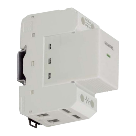
5SD7 411-1
RSC
5SD7 418-1
4,5 Nm
Torque 40-50 lbs-in
acc. UL
0,5 m
PE
Ground
PAS
L1
5SD7 411-1
RSC
Wechsler
U
max
PDT
Inverseur
C. inversor
U
max
12
11
14
0,25 Nm
Torque 2-40 Ibs-in
7mm
2
0.14 mm
- 1.5 mm
AWG 28-16; AWG 30-14 (UL)
Netzsystem / net system
Anforderungsklasse / requirement class
Blitzschutzklasse / lightning protection level
Ableiterbemessungsspannung U
max. continous operating voltage U
Nennspannung U
Blitzstoßstrom I
imp
lightning peak current I
Nennstoßstrom I
n
nominal discharge current I
Schutzpegel U
/ protection level U
p
Kurzschlussfestigkeit bei max. Vorsicherung I
Short circuit resistance with max. backup fuse I
Folgestromlöschfähigkeit I
follow current limitation I
Temperaturbereich / operating temperature range
Schutzart / degree of protection
Max. Sicherung / max. back-up fuse
∅ min. L, N, PE
∅ max. L, N, PE
Ersatzstecker / replacement
green ⇒ ok
red ⇒ defekt
⇒
Recycling
TN-C
L
B
Parallel wiring /
Anschluss im Stich
DIN VDE 0100-534 ⇒ (a, b ≤ 0,5 m)
IEC 60364-5-53;
CEI 81-8:2002-02
/I
max
AC: 250 V/ 1 A
/I
max
DC: 125 V/ 0.2A
7mm
2
MLFB
SPD Type 1 gemäß EN 61643-11:2002 + A11:2007
/
C
C
/ nominal voltage U
N
N
(10/350)μs /
(10/350)μs
imp
(8/20)μs /
(8/20)μs
n
p
p
p
/
fi
fi
AWG13-2
AWG 12-2 (UL)
⇒ (a + b ≤ 0,5 m)
Protection conductor bar
L1
Für eine sichere Funktion sind
auch nicht genutzte Klemmstel-
len anzuziehen.
To ensure safe and reliable
functioning, unoccupied
terminal points should also be
screwed tight.
Z-NR: 9661422_01/24.11.08 Printed in Germany
5SD7 411-1
TN-C
L1, PEN
B nach VDE 0675-6-11:2007;
SPD class I gemäß IEC 61643-1:2005;
III / IV, 50 kA
350 V AC 50/60 Hz
240/415 V AC 50/60 Hz
25 kA
25 kA
≤ 1.5 kV
50 kA
rms
25 kA (350 V AC)
50 kA (264 V AC)
-40 ... +80°C
IP20
Application A: 125 A gL/gG - Seriell
Application B: 315 A gL/gG - Parallel
18 mm
2
18 mm
2.5 mm
2.5 mm
2
35 mm
25 mm
5SD7 418-1
0,5 m
a
b
0,5 m
PAS
Back-up Fuse / Vorsicherung
F1
F2
S
S
2
PE
A gL/gG
A gL/gG
2
2
mm
mm
25
10
16
35
10
16
40
10
16
50
10
16
63
10
16
80
10
16
100
16
16
125
16
16
160
25
25
200
35
35
250
35
35
315*
160
50
50
> 315
50
50
* max. Vorsicherung 315 A nach
IEC 61643-1
* max. fuse 315 A according to
IEC 61643-1
vom Hersteller empfohlene
Sicherung
160
fuse recommended by the manu-
facturer
253676.41.98 "02"
2
2
L
Werbung

Verwandte Anleitungen für Siemens 5SD7 411-1


Inhaltszusammenfassung für Siemens 5SD7 411-1
- Seite 1 5SD7 411-1 MLFB 5SD7 411-1 Montageanleitung Netzsystem / net system TN-C L1, PEN Installation Instruction Anforderungsklasse / requirement class B nach VDE 0675-6-11:2007; SPD class I gemäß IEC 61643-1:2005; SPD Type 1 gemäß EN 61643-11:2002 + A11:2007 Blitzschutzklasse / lightning protection level...
- Seite 2 D - 93055 Regensburg 5SD7 411-1 sind auf dem AEC-Prinzip koordinierte Ableiter, bestehend aus steckbaren 5SD7 411-1 sono scaricatori secondo il principio AEC, costituiti da scaricatori di correnti Blitzstromableitern 5SD7 418-1 mit gekapselten Funkenstrecken. atmosferiche a innesto 5SD7 418-1 con spinterometri incorporati.