Werbung
Quicklinks
IT ALIANO
Caratteristiche
-
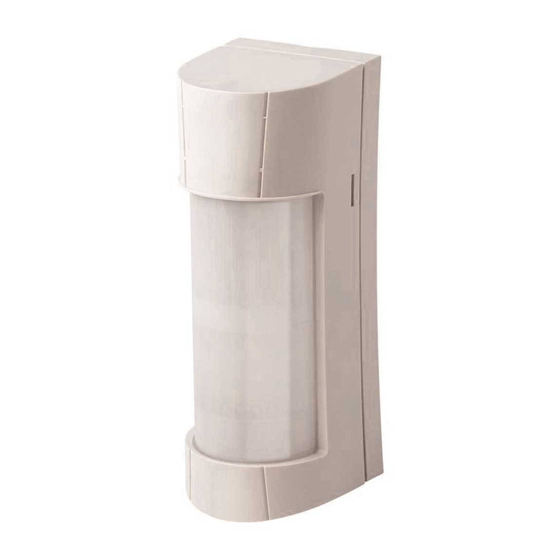
E' un rilevatore volumetrico di movimento, con collegamento filare, composto da un doppio infrarosso e da una microonda planare, ideato per
la protezione sia interna che esterna.
-
E' progettato per la protezione di aree esterne e per ridurre al minimo il rischio di falsi allarmi dovuti a condizioni meteorologiche, elementi ambientali,
animali in libertà, ecc...
-
E' dotato di un buzzer e di led per dare una segnalazione ottico-acustica (Walk Test).
-
E' dotato di:
•
Compensazione termica, il sensore regola automaticamente le prestazioni del sistema al variare della temperatura ambiente, ciò nonostante le
prestazioni del sensore possono variare sensibilmente in relazione a particolari intervalli di temperature.
•
Filtri di protezione contro la luce bianca e quella solare, per ottimizzare la lettura degli infrarossi
•
Accelerometro, per la segnalazione dello strappo (non rileva la vibrazione). Una eventuale rimozione non autorizzata viene segnalata dal
sensore come TAMPER.
•
Antimascheramento infrarosso, formato da un ricevitore RX ed un tramettitore TX ad infrarossi attivi, che rileva gli ostacoli posti di fronte al
sensore fino ad una distanza di circa 7 cm. La calibrazione avviene alla chiusura del TAMPER (Contenitore e, se presente, Antistrappo) e dura
circa 40 secondi, durante i quali il led Giallo lampeggia lentamente. La segnalazione viene generata dopo circa 30 secondi dal rilevamento
dell'ostacolo, durante i quali il led Giallo lampeggia velocemente, se il sensore nel frattempo non genera un allarme. Durante la segnalazione di
Antimascheramento, il led Giallo è acceso fisso. La segnalazione si resetta alla rimozione dell'ostacolo.
NOTA: Se il led GIALLO rimane acceso FISSO durante la fase di Calibrazione Antimask, indica che il sensore non riesce ad effettuare corretta-
mente la procedura a causa della luce solare che colpisce la lente, aprire e richiudere il TAMPER per ripetere la procedura facendo ombra al sensore.
-
E' dotato di un ingresso ausiliario AUX per gestire un ulteriore ingresso di allarme o il circuito di antistrappo del sensore stesso
-
E' dotato di Mascherine Adesive Oscuranti per ridurre l'angolo di copertura, o mascherare una zona specifica
-
Può essere dotato di una TETTOIA protettiva opzionale (Mod. SSC PROTEZIONE FRONT)
Installazione
Per l'apertura e l'installazione del sensore vedi le illustrazioni stampate nella parte interna della confezione.
Caratteristiche tecniche
Tensione nominale
12 V =
Tensione di alimentazione
Max: 15 V = / Min: 10,5 V =
Assorbimento
21 mA in quiete / 25 mA in allarme
Copertura modello Spectrum DT AM
100° su 12 metri effettivi
Copertura modello Spectrum DT SSL
100° su 12 metri effettivi
Antimascheramento infrarosso
sì
Frequenza microonda
- Paesi della Comunità Europea
eccetto Germania: 10,525 GHz
- Germania: 9,350 GHz
Segnale emesso dalla microonda
Impulsato
Altezza installazione modello Spectrum DT AM
da 1,2 a 1,5 metri da terra
Altezza installazione modello Spectrum DT SSL
2,2 metri da terra
Condizioni funzionamento scheda elettronica
-25° C / +55° C
Peso (grammi)
260
Dimensioni senza TETTOIA (millimetri) (PxLxH)
68,3 x 75,4 x 189,4
Dimensioni con TETTOIA (millimetri) (PxLxH)
87,3 x 75,4 x 189,4
Grado di protezione
IP55
Prima alimentazione
Alla prima alimentazione il sensore rimane in blocco per circa 60 secondi, durante i quali i led lampeggiano.
Modalità di funzionamento
AND: Il sensore attiva il relè di allarme ed il led blu solo quando entrambe le tecnologie andranno in allarme.
Portata Infrarosso (vedi FIG. F dettaglio 1)
-
Spectrum DT AM:
Installazione da 1,2 a 1,5 metri dal terreno (FIG. B): è possibile modificare la portata dell'infrarosso da 12 fino a 3 metri variando
l'altezza del PIR inferiore da 5 fino a 1 e, se necessario, posizionando il DIP 1 in ON.
Per variare l'altezza del PIR è necessario allentare la Vite 1 in FIG. D. Rifissarla per bloccare il PIR nella posizione desiderata.
-
Spectrum DT SSL:
Installazione a 2,2 metri dal terreno (FIG. C): la portata è fissa a 12 metri, il PIR inferiore dev'essere necessariamente sulla
posizione 1 (vedi Copertura).
NOTA: L'efficacia massima della copertura, si ha installando il sensore perpendicolarmente al terreno.
Portata Microonda (Vedi Trimmer MW in FIG. D)
La portata della microonda è regolabile tramite il Trimmer MW. Aumenta in senso orario.
Copertura (FIG. A)
Spectrum DT AM: Installazione da 1,2 a 1,5 metri dal terreno (FIG. B), la scheda elettronica può essere ruotata orizzontalmente per variare l'angolo
di copertura che rimane comunque di 100° su 180° disponibili (vedi FIG. F dettaglio 2). Per ruotare la scheda è necessario allentare la Vite 2 in FIG.
D, rifissarla per bloccare la scheda nella posizione desiderata.
Spectrum DT SSL: Installazione a 2,2 metri dal terreno (FIG. C), la copertura è di 100°. La scheda elettronica deve essere fissata nella posizione
orizzontale a 0° (vedi FIG. F dettaglio 2).
In alcune circostanze il sensore potrebbe rilevare bersagli in movimento, specialmente nelle vicinanze, ad angolazioni oltre i 100° nominali di
copertura. Si consiglia perciò di mascherare preventivamente con gli appositi adesivi in dotazione i settori di lente che non fanno parte della
zona di rilevazione desiderata.
Morsettiera (FIG. B)
-
Negativo di alimentazione 12 V =
+
Positivo di alimentazione 12 V =
C / NC
Uscita di segnalazione Allarme. Contatto normalmente chiuso (vedi jumper ALARM nella tabella E)
NOTA: se il jumper S1 è in posizione 2 (vedi tabella E), questo contatto risulta in serie a quello di TAMPER
AM AM
Uscita di segnalazione Antimascheramento. Contatto normalmente chiuso (vedi jumper ANTIMASK nella tabella E)
T T
Uscita di segnalazione di Tamper. Contatto normalmente chiuso (vedi jumper TAMPER nella tabella E)
NOTA: se il jumper S1 è in posizione 2 (vedi tabella E), questo contatto risulta in serie a quello di ALLARME
B
Ingresso che permette al sensore di avere il riferimento dello stato della centrale. Per gestire questa informazione, a centrale spenta
questo ingresso deve risultare chiuso a positivo. In questa condizione il relè di allarme rimane chiuso, la microonda viene disalimen-
tata e, nel caso di un allarme, il led ed il buzzer non si attivano
AUX
AUX è un ingresso con riferimento a negativo che attiva o il relè di Allarme o quello di Tamper (vedi DIP 5)
Resistenze di bilanciamento (Tabella E)
Le uscite ALARM, TAMPER e ANTIMASK possono essere configurate C/NC (Jumper aperto) oppure con delle resistenze di bilanciamento in parallelo
(Jumper chiuso in base al valore di resistenza da impostare). Inoltre possono essere separate o collegate in serie internamente.
Alcuni esempi di
configurazioni sono riportati nella Tabella E:
Schema 1. I contatti di Allarme, Tamper e Antimask risultano indipendenti tra loro
Schema 2. I contatti di Allarme e di Tamper risultano in serie tra loro (è necessario eseguire un ponte a filo tra l'Allarme e il Tamper). L'Antimask è indipendente.
Schema 3. I contatti di Allarme e di Tamper risultano in serie tra loro (è necessario inserire uno dei 4 jumper relativi alle resistenze Tamper). L'Antimask è indipendente.
Schema 4. I contatti di Allarme e di Antimak risultano in serie tra loro. Il Tamper è indipendente.
Schema 5. I contatti di Allarme, Tamper e Antimask risultano in serie tra loro (è necessario inserire uno dei 4 jumper relativi alle resistenze Tamper).
LED (FIG. D)
LED BLU: durante l'inizializzazione questo led lampeggia per 60 secondi. Si accende per 1 secondo quando il sensore va in allarme.
LED GIALLO: durante l'inizializzazione e la calibrazione dell'antimask questo led lampeggia ma resta acceso fisso se la
corretto. Lampeggia ogni uno o due secondi quando il sensore rileva una condizione di mascheramento.
Dip Switch (FIG. D)
Ridotta: da utilizzare per ridurre ulteriormente la portata se lo spostamento della slitta (vedi
ON
FIG. F dettaglio 2) non fosse sufficiente. La microonda esegue un'analisi digitale dei se-
DIP 1
PORTATA / SENSIBILITÀ
gnali più severa che tende ad escludere l'oscillazione delle piante sotto l'azione del vento.
OFF
Default
Normale
INGRESSO AUX
ON
Gestione ingresso AUX abilitata
DIP 2
(Abilitazione)
OFF
Default
Gestione ingresso AUX disabilitata
ON
Antimask abilitato
DIP 3
ANTIMASK
OFF
Default
Antimask escluso
ON
Accelerometro abilitato
DIP 4
ACCELEROMETRO
OFF
Default
Accelerometro escluso
ON
Ingresso AUX attiva il relè di Allarme
INGRESSO AUX
DIP 5
(Gestione)
OFF
Default
Ingresso AUX attiva il relè di Tamper
LED GIALLO
ON
Led Giallo Allarme Microonda
DIP 6
(Gestione)
OFF
Default
Led Giallo Allarme Antimask
LED BLU e GIALLO
ON
Default
Led Blu e Led Giallo abilitati
DIP 7
(Abilitazione)
OFF
Led Blu e Led Giallo esclusi
ON
Default
Buzzer abilitato
DIP 8
BUZZER
OFF
Buzzer escluso
In caso di installazioni su tetti di capannoni o edifici in genere, particolarmente dove ci sono lucernari o altre superfici riflettenti o pavimentazioni in asfalto
che subiscono forte riscaldamento per l'irraggiamento del sole, si raccomanda usare la modalità a sensibilità ridotta dell'infrarosso, in quanto, tali fattori, fa-
voriscono l'insorgenza di falsi allarmi. In ogni caso, regolare sempre correttamente la sensibilità della microonda al valore minimo indispensabile e non oltre.
Tamper
-
Il TAMPER antiapertura del coperchio è già installato e cablato di fabbrica.
-
Il TAMPER antistrappo opzionale da installare sul fondo del sensore (Cod.1135112) è consigliato il collegamento tra i morsetti AUX e - (negativo)
AVS ELECTRONICS S.p.a. si riserva il diritto di apportare modifiche in qualsiasi momento e senza preavviso.
SPECTRUM DT AM
SPECTRUM DT SSL
A
Dichiarazione di Conformità
La dichiarazione di conformità può
essere consultata nell'area riservata
del sito
AVS Electronics.com.
L'alimentazione deve provenire da
un circuito a bassissima tensione di
sicurezza ed avente le caratteristiche
di una sorgente a potenza limitata
protetta da fusibile.
10m
INSTALLAZIONE E MANUTENZIONE
12m
DEVONO ESSERE FATTE
DA PERSONALE
QUALIFICATO.
SP Lens 1,2 m
1,2 m
B
0m 1m
2m
1,2 m
SP Lens 2,2 m
2,2 m
1,2 m
C
0m 1m
2m
0m 1m
2m
0m 1m
2m
-
+
C NC
AM
AM
T T B
AUX
TAMPER
ALARM
ANTIMASK
1 2 3 4
1 2 3 4
1 2 3 4
1 2 3
S2
S1
LD1 LD2
MW
D
calibrazione non avviene in modo
1
2
3
4
5
1
TAMP.
2
Curtarolo (Padova) Italy
www.avselectronics.com
5m
5m
10m
12m
0.8 m
3m
4m
5m
6m
7m
8m
9m 10m 11m 12m
PIR
3m
4m
5m
6m
7m
8m
9m 10m 11m 12m
PIR
3m
4m
5m
6m
7m
8m
9m 10m 11m 12m
3m
4m
5m
6m
7m
8m
9m 10m 11m 12m
E
TAMPER
ALARM
ANTIMASK
10 KOHM
5,6 KOHM
-
+
C NC
T T B
AM
AM
AUX
4,7 KOHM
-
+
C NC
T T B
AM
AM
AUX
2,2 KOHM
TAMPER
ALLARM
ANTIMASK
1 2 3 4
1 2 3 4
1 2 3 4
N.C.
-
+
TAMPER
ALLARM
C NC
AM
ANTIMASK
AM
T T B
AUX
-
+
1 2 3 4
1 2 3 4
1 2 3 4
C NC
T T B
1 2 3
AM
AM
-
+
S1
S2
C NC
T T B
AM
AM
AUX
1
-
+
C NC
T T B
AM
AM
AUX
1 2 3
S1
TAMPER
S2
ALLARM
ANTIMASK
1 2 3 4
1 2 3 4
1 2 3 4
-
+
C NC
T T B
AM
AM
AUX
TAMPER
ALLARM
ANTIMASK
-
+
C NC
T T B
1 2 3 4
1 2 3 4
1 2 3 4
TAMPER
ALLARM
ANTIMASK
AM
AM
-
+
-
+
TAMPER
ALLARM
1 2 3
C NC
T T B
C NC
T T B
1 2 3 4
S2
AM
1 2 3 4
AM
2
1 2 3 4
AUX
AM
S1
AM
AUX
1 2 3 4
1 2 3 4
TAMPER
1 2 3
TAMPER
ALLARM
ANTIMASK
S1
S2
-
+
C NC
T T B
AM
AM
AUX
1 2 3 4
1 2 3 4
1 2 3
1 2 3 4
S2
-
+
S1
C NC
T T B
AM
AM
AUX
TAMPER
ALLARM
ANTIMASK
TAMPER
ALLARM
ANTIMASK
-
+
LD1 LD2
1 2 3 4
1 2 3 4
1 2 3 4
1 2 3 4
1 2 3 4
1 2 3 4
C NC
1 2 3
T T B
-
+
TAMPER
AM
ALLARM
AM
-
+
C NC
T T B
S2
1 2 3
AM
AM
AUX
S1
C NC
AM
AM
T T B
AUX
S1
S2
ALARM
3
1 2 3 4
1 2 3 4
LD1 LD2
TAMPER
ALLARM
ANTIMASK
1 2 3 4
1 2 3
1 2 3 4
1 2 3 4
X
X
1 2 3
TAMPER
ALLARM
ANTIMASK
-
+
S1
S2
S1
S2
C NC
T T B
AM
AM
AUX
1 2 3 4
1 2 3 4
TAMPER
1 2 3 4
-
+
C NC
TAMPER
T T B
ALLARM
ANTIMASK
TAMPER
ALLARM
ANTIMASK
AM
AM
AUX
-
+
1 2 3 4
1 2 3
1 2 3 4
1 2 3 4
S2
C NC
1 2 3
T T B
1 2 3 4
1 2 3 4
1 2 3 4
S1
LD1 LD2
AM
AM
-
+
TAMPER
ALLARM
S2
-
+
S1
1 2 3
C NC
T T B
C NC
T T B
S2
ALARM
AM
AM
AUX
AM
S1
AM
AUX
4
TAMPER
ALLARM
ANTIMASK
1 2 3 4
1 2 3 4
LD1 LD2
X
X
1 2 3 4
1 2 3
1 2 3 4
1 2 3 4
1 2 3
S2
TAMPER
S2
ALLARM
-
+
S1
ANTIMASK
LD1 LD2
S1
C NC
T T B
AM
AM
AUX
1 2 3 4
1 2 3 4
ANTIMASK
1 2 3 4
TAMPER
ALLARM
ANTIMASK
TAMPER
ALLARM
ANTIMASK
1 2 3
1 2 3 4
S1
1 2 3 4
S2
1 2 3 4
1 2 3 4
1 2 3 4
1 2 3 4
-
+
LD1 LD2
1 2 3
-
TAMPER
+
ALLARM
C NC
AM
AM
T T B
AUX
S2
1 2 3
S1
C NC
T T B
S1
S2
ALARM
AM
AM
1 2 3 4
1 2 3 4
TAMPER
ALLARM
ANTIMASK
LD1 LD2
LD1 LD2
5
1 2 3 4
1 2 3
1 2 3 4
1 2 3 4
1 2 3
S1
S2
S1
S2
X
X
X
X
ANTIMASK
TAMPER
ALLARM
ANTIMASK
LD1 LD2
1 2 3
1 2 3 4
1 2 3 4
1 2 3 4
S1
LD1 LD2
S2
1 2 3
S2
S1
TAMPER
TAMPER
ALLARM
LD1 LD2
LD1 LD2
1 2 3
1 2 3 4
1 2 3 4
S2
S1
1
2
0°
LD1 LD2
1
3
1 - 3 mt
LD1 LD2
2
4
F
2 - 5 mt
1 2 3
5°
S2
3
S1
5
3 - 7 mt
LD1 LD2
LD1 LD2
4
18°
1
4 - 9 mt
5
2
31°
LD1 LD2
5 - 12 mt
1
3
45°
1
2
4
2
3
LD1 LD2
5
2
4
3
1
4
5
2
5
1
1
3
2
2
4
1
3
3
5
1
4
4
1
2
5
5
2
3
1
1
3
4
2
ENGLISH
Features
-
It is a wired volumetric motion detector with dual infrared sensor and planar microwave designed for both internal and external protection.
-
Sensor designed for the protection of outdoor areas and the minimisation of the risk of false alarms due to weather conditions, environmental ele-
ments, animals, etc
It has a buzzer and LED for the optical and sound alarm signalling function (Walk Test).
-
-
It is equipped with:
•
Thermal compensation, whereby the sensor automatically adjusts the performance of the system to compensate for changes in ambient tempe-
rature. Its own performance can, however, vary considerably in relation to particular temperature ranges.
•
White light and solar filters to optimise performance of the infrared sensors
•
Accelerometer that indicates tampering (does not detect vibration). The sensor indicates unauthorised removal as a TAMPER event.
•
Anti-masking with infrared, comprising an RX receiver and a TX transmitter with active infrared that detect obstacles at a distance of about 7 cm
in front of the sensor. Calibration occurs after closing of the TAMPER device (Container and Anti-tear device, when applicable) and takes about 40
seconds, during which time the yellow LED flashes slowly. The presence of an obstacle is indicated about 30 seconds after it is detected, during
which time the yellow LED flashes quickly if the sensor does not generate an alarm in the meantime. The yellow LED remains steady during the
anti-masking signal. Removing the obstacle stops the signal.
NOTE: if the YELLOW LED remains on and STEADY during the Antimask Calibration phase, this means the sensor is unable to complete the
procedure properly due to the reflection of light on the lens. Open and close the TAMPER to repeat the procedure, shading the sensor.
-
It has an AUX auxiliary input for managing another alarm input or the anti-tear circuit of the same sensor
-
It has Adhesive Masks for reducing the angle of coverage or masking a specific area
-
It can be equipped with an optional protective ROOF (Mod. SSC FRONT PROTECTION)
Installation
For opening and installation of the sensor see the illustrations printed on the inside of the package.
Technical Features
Rated voltage
Power supply
MW
Absorption
Coverage area with Spectrum DT AM:
Coverage area with Spectrum DT SSL:
Anti-masking with infrared
Microwave frequency
PIR
Microwave signal
Height of installation with Spectrum DT AM
Height of installation with Spectrum DT SSL
Operating conditions of the printed circuit board
Weight (grams)
Dimensions without ROOF (millimetres) (WxLxH)
Dimensions with ROOF (millimetres) (WxLxH)
Degree of protection
Initial start-up
The sensor is kept on standby for about 60 seconds, during which time the LEDs blink.
Operating mode
AND: The sensor activates the alarm relay and blue LED only when both the technologies enter alarm mode.
Infrared capacity (see FIG. F detail 1)
-
Spectrum DT AM: Installation 1.2 to 1.5 metres above the ground (FIG. B): it is possible to change infrared capacity from 12 up to 3 meters by
changing the height of the lower PIR from 5 to 1 and, if necessary, by placing the DIP 1 to ON.
To change the height of the PIR, loosen Screw 1 in FIG. D. Refasten it to lock the PIR in the required position.
-
Spectrum DT SSL: Installation 2.2 metres above the ground (FIG. C): capacity is set at 12 metres, the lower PIR must be at position 1 and
horizontal at 0° (see Coverage).
NOTE: The sensor should ideally be installed perpendicular with the ground for optimal adjustment of capacity.
0.8 m
Microwave capacity (See MW Trimmer in FIG. D)
Microwave capacity can be adjusted at the MW Trimmer. Turn clockwise to increase.
0.8 m
Coverage (FIG. A)
Spectrum DT AM: Installation 1.2 to 1.5 metres above the ground (FIG. B), the printed circuit board can be turned horizontally to change the angle of
coverage which remains in any case 100° out of the available 180° (see FIG. F detail 2). To turn the printed circuit board, loosen Screw 2 in FIG. D.
Refasten it to lock the printed circuit board in the required position.
Spectrum DT SSL: Installation 2.2 metres above the ground (FIG. C), the coverage is of 100°. The printed circuit board must be locked in the horizontal
position at 0° (see FIG. F detail 2).
In some circumstances, the sensor could detect moving targets, especially closed, at angles above 100 ° of nominal coverage. It is better to
mask preventively the lens sectors which are not part of the desired detection area, thanks to appropriate provided stickers.
Terminal block (FIG. B)
-
Negative power supply 12 V =
+
Positive power supply 12 V =
C / NC
Alarm signal output. Normally closed contact (refer to the ALARM jumper in table E)
NOTE: if jumper S1 is in position 2 (refer to table E), this contact is in series with the TAMPER one
AM AM
Antimask signalling output. Normally closed contact (refer to the ANTIMASK jumper in table E)
T T
Tamper signal output. Normally closed contact (refer to the TAMPER jumper in table E)
NOTE: if jumper S1 is in position 2 (refer to table E), this contact is in series with the ALARM one
B
Input that allows the sensor to obtain the status reference of the central control unit. In order to manage this information, this input
must be positively closed when the central control unit is turned off. n this condition, the alarm relay is closed, the microwave is off
and, in the case of an alarm, the LED and buzzer are not activated
AUX
AUX is an input with negative reference that activates either the Alarm relay or the Tamper relay (see DIP 5)
Balancing resistors (Table E)
AUX
The ALARM, TAMPER and ANTIMASK outputs can be configured C/NC (Jumper open) or with balancing resistors in parallel (Jumper closed on the
basis of the resistance value to be set). They can also be separated or connected in series internally.
Some examples of configuration are given in Table E:
Scheme 1. The Alarm, Tamper and Antimask contacts are independent of each other
Scheme 2. The Alarm and Tamper contacts are in series with each other (It is necessary to perform a wire bridge between the Alarm and the Tamper).
AUX
The Antimask contact is independent.
ANTIMASK
Scheme 3. The Alarm and Tamper contacts are in series with each other (It is necessary to insert one of 4 jumpers relating to Tamper resistance). The
1 2 3 4
Antimask contact is independent.
Scheme 4. The Alarm and Antimask contacts are in series with each other. The Tamper contact is independent.
Scheme 5. The Alarm, Tamper and Antimask contacts are in series with each other (It is necessary to insert one of 4 jumpers relating to Tamper resistance).
LED (FIG. D)
ANTIMASK
AUX
BLUE LED: during initialization this LED blinks for 60 seconds (see note below for AM model). It goes ON for 1 second when there is an alarm.
1 2 3 4
YELLOW LED: during sensor initialization and antimask calibration this LED blink, but stay ON if the antimask calibration is not correct and must be repeated.
They blink each one or two seconds when detecting a masking condition.
-
Dip Switch (FIG. D)
Reduced: to be used to further reduce the flow rate if the displacement of the slide (see
AUX
ANTIMASK
ON
FIG. F detail 2) was not enough. The microwave section performs a more severe digital
DIP 1
CAPACITY / SENSIVITY
signal analysis that tends to exclude the oscillations from plants under the wind action.
1 2 3 4
OFF
Default
Normal
AUX INPUT
ON
Management of AUX input enabled
DIP 2
(Enabling)
OFF
Default
Management of AUX input disabled
ANTIMASK
ON
Antimask enabled
DIP 3
ANTIMASK
AUX
OFF
Default
Antimask disabled
1 2 3 4
ON
Accelerometer enabled
DIP 4
ACCELEROMETER
OFF
Default
Accelerometer disabled
LD1 LD2
ON
The AUX input enables the Alarm relay
AUX INPUT
DIP 5
(Management)
OFF
Default
The AUX input enables the Tamper relay
ANTIMASK
ON
Yellow LED Microwave alarm
YELLOW LED
DIP 6
1 2 3 4
(Gestione)
OFF
Default
Yellow LED Antimask alarm
ON
Default
Blue LED and Yellow LED enabled
BLUE and YELLOW LED
DIP 7
LD1 LD2
(Enabling)
OFF
Blue LED and Yellow LED disabled
ON
Default
Buzzer enabled
DIP 8
BUZZER
OFF
Buzzer disabled
In case of roof installations in industrial or civil buildings in general, especially if skylights or other reflective surfaces are present, and/or asphaltic
coated grounds showing strong heating by sun irradiation exist, it is recommended to set the reduced sensitivity mode of the infrared, because those
LD1 LD2
factors favor the insurgence of false alarms. Anyway, always adjust correctly the microwave sensitivity to the minimum possible value for the needed
coverage and not higher.
Tamper
-
The anti-opening TAMPER device of the cover is installed and wired at the factory.
-
The optional anti-tear TAMPER device is to be installed at the base of the sensor (Code 1135112) and it is advisable to make the connection between
LD1 LD2
the AUX and - (negative) terminals
AVS ELECTRONICS S.p.a. reserves the right to make changes at any time without prior notice
ist0919V2.1
LD1 LD2
12 V =
Max: 15 V = / Min: 10,5 V =
Declaration of Conformity
21 mA idle / 25 mA in alarm mode
The declaration of conformity is available
100° effectively for 12 metres
for reference in the reserved area of the
100° effectively for 12 metres
site AVS Electronics.com.
yes
- European Community countries
except Germany: 10.525 GHz
- Germany: 9,350 GHz
The power supply must come from a
Pulsed
very low voltage security circuit with
1.2 to 1.5 metres above the ground
the features of a limited power source
2.2 metres above the ground
protected by a fuse.
-25° C / +55° C
INSTALLATION AND MAINTENANCE
260
MUST BE CARRIED OUT BY
68,3 x 75,4 x 189,4
QUALIFIED PERSONNEL
87,3 x 75,4 x 189,4
IP55
Werbung

Verwandte Anleitungen für AVS Electronics SPECTRUM DT AM

Inhaltszusammenfassung für AVS Electronics SPECTRUM DT AM
- Seite 1 AND: Il sensore attiva il relè di allarme ed il led blu solo quando entrambe le tecnologie andranno in allarme. Spectrum DT AM: Installation 1.2 to 1.5 metres above the ground (FIG. B): it is possible to change infrared capacity from 12 up to 3 meters by Portata Infrarosso (vedi FIG.
- Seite 2 DIP 1 auf ON. Spectrum DT AM: Installation de 1,2 à 1,5 mètres du sol (FIG. B) : il est possible de modifier la portée de l’infrarouge de 12 à 3 mètres en variant Spectrum DT SSL: Instalación a una altura de 2,2 metros desde el suelo (FIG. C): el alcance es fijo en 12 metros, el PIR inferior debe estar Zum Ändern des PIR muss die Schraube 1 in ABB.