Werbung
Quicklinks
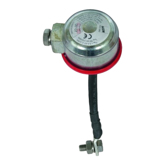
INSTALLATION INSTRUCTIONS
Technical Data / Technische Daten
Isolating spark gap, Class N acc.
Rated power-frequency withstand voltage/
Bemessungs-Stehwechselspannung
to EN 62561-3
Lightning impulse sparkover voltage/ (1,2/50 µs )
Types:
Ansprech-Blitzstoßspannung
EXFS L 100, Part No. 923 060
Lightning impulse current/ (10/350 µs )
EXFS L 200, Part No. 923 061
Blitzstoßstrom
EXFS L 300, Part No. 923 062
Operating temperature range/
Betriebstemperaturbereich
EXFS L ....Special lengths/Sonderlängen
Degree of protection/
Schutzart
Ex component:
Connection/
II 3 G Ex nC IIC T4 Gc
Anschlussgehäuse
Certificates:
DEKRA 11ATEX0146 X
IECEx DEK 11.0063X
(s. www.dehn.de)
Standards:
for ATEX: EN 60079-0:
2009
EN 60079-15: 2010
for IECEx: IEC 60079-0: 2007
IEC 60079-15: 2010
Ambient temperature range:
-20°C ... +60°C for temperature class T4
Parallel installation/ Parallel geführter Anbau
Fig.1
H
L
IF 1
IF 3
C
C
H = (H
≥
H
S
0.5 L
L
IF 3
C
connection bracket/
IF 3
Anschlussbügel
IF 1
insulating flange/
Isolierflansch
Note:
³
The insulating flange and connection bracket IF1/IF3 can be
S
0,5 L
L
electrically connected by screwed (screw flanges) or welded
connections (insulating piece)!
Achtung:
Die leitende Verbindung zwischen dem Isolierflansch und dem
Anschlussbügel IF 1/IF 3 kann je nach Bauform durch
Schraubverbindungen (Schraubflansch) oder durch
Schweißverbindungen (Isolierstück) hergestellt werden!
U
300 V
w/AC
U
≤ 2,5 kV
r imp
I
50 kA
imp
-20° ... + 80° C
IP 54
M 10
Note:
Only vertical installation!
Hinweis:
Nur senkrechte
Einbaulage möglich!
Installation notes / Installationshinweise
Voltage drop at connecting cables depending on the cable length and the impulse current steepness.
Spannungsfall an Anschlußleitungen in Abhängigkeit von der Leitungslänge und der Steilheit des Stoßstroms.
B
A
10 Nm
H = (H
H
) /
min +
max
IF 1/IF 3
lock the nut!/
L
Connecting Cable Length [m] /Länge Anschlussleitung [m]
IF 1
gegenhalten!
IF 3
Voltage Drop [kV] at 10 kA/µs, LPL I / Spannungsfall [kV] bei 10 kA/µs, BSK I
Voltage Drop [kV] at 7.5 kA/µs, LPL II / Spannungsfall [kV] bei 7.5 kA/µs, BSK II
H
Voltage Drop [kV] at 5 kA/µs, LPL III / Spannungsfall [kV] bei 5 kA/µs, BSK III
A
screw/Schraube
The sum of the voltage drop at the connecting cables and the lightning impulse sparkover voltage must not exceed the insulation strength of the test joint.
M 10
B
spring washer/
H
) /
Die Summe aus Spannungsfall an den Anschlussleitungen und der Ansprech-Blitzstoßspannung darf die Isolationsfestigkeit der Trennstelle nicht überschreiten.
min +
max
Federring
Note: Observe the requirements of AfK recommendation No. 5.
IF 1
A
L
Hinweis: Die Vorgaben entsprechend der AfK-Empfehlung Nr. 5 (07/2010) sind zu beachten.
³
S
0,5 L
L
Requirements on the connecting cables:
B
H
• Capable of carrying lightning currents
• No ignition sparks
10 Nm
• Situated in parallel and as close as possible to the insulating piece
cable lug/
Kabelschuh
• Connected using the shortest path
• Protected against accidental bridging (for example by means of tools)
Suitable connection points on pipelines are:
• Welded lugs, pins
• Threaded holes in the flanges to receive bolts
• Observe connection clamps / pipe clamps / absence of ignition sparks
Accessories / Zubehör
IF 3
IF 1
Part No. 923 2xx
Part No. 923 3xx
xx = d1
xx = d1
connection bracket/
Anschlussbügel
d1
d1
*
*
max. 42 mm
max. 62 mm
top view/Draufsicht
side view/Seitenansicht
*
available diameters s. www.dehn.de
verfügbare Durchmesser s. www.dehn.de
connection height "H" of the
Size/Größe
connection brackests (m) /
Anschlusshöhe "H" der ver-
fügbaren Anschlussbügel (m)
IF 1
IF 3
1
0,08
0,1
2
0,1
0,12
3
0,14
---
Publication No. 1010 / UPDATE 11.14 Mat. No. 3000233
Vertical installation
/ Senkrecht geführter Anbau
Fig. 2
pipe/Rohr
IF 1
S
L
IF 3
L
IF 1
H
Note:
The spark gap can be tested for correct operation by means of an insulation
resistance meter (strictly follow the instructions for use of the insulation
resistance meter). The spark gap may only be tested (measured) in an
uninstalled state and outside the Ex zone (R
iso
Hinweis:
Die Funkenstrecke kann mit einem Isolationsmessgerät auf Funktion geprüft
werden.
Die Überprüfung darf nur unter Beachtung der Bedienungsanleitung des
Isolationsmessgerätes erfolgen. Die Überprüfung (Messung) darf nur im
ausgebauten Zustand der Funkenstrecke und außerhalb der Ex-Zone erfolgen
(R
≥
500 k
Ω /
500 V).
iso
0,10 0,20 0,30 0,50 0,75 1,00 1,25 1,50
1,0
2,0
3,1
5,1
7,6
10,1
12,6
15,1
0,8
1,5
2,3
3,8
5,7
7,6
9,5
11,4
0,5
1,0
1,5
2,5
3,8
5,1
6,3
7,6
Anforderung Anschlusstechnik
• blitzstromtragfähig,
• zündfunkenfrei,
• unmittelbar parallel und eng am Isolierstück angeordnet,
• auf kürzesten Weg angeschlossen,
• gegen zufälliges Überbrücken (z.B. durch Werkzeuge) gesichert
Geeignete Anschlusspunkte an Rohrleitungen sind
• angeschweißte Fahnen, Bolzen
• Gewindebohrungen in den Flanschen zur Aufnahme von Schrauben
• Anschlußschellen / Bandrohrschelle / Zundfunkenfreiheit beachten
© COPYRIGHT 2014 DEHN + SÖHNE / protected by ISO 16016
Fig. 3
≥ 500
k
Ω
500 V).
/
2,00 3,00
4,00 4,25
20,2
30,2
40,3 42,8
15,2
22,7
30,3 32,2
10,1
15,1
20,2 21,4
p.t.o.
Safety
Instructions
Werbung

Verwandte Anleitungen für Dehn EXFS L Serie


Inhaltszusammenfassung für Dehn EXFS L Serie
- Seite 1 Die leitende Verbindung zwischen dem Isolierflansch und dem • Anschlußschellen / Bandrohrschelle / Zundfunkenfreiheit beachten Anschlussbügel IF 1/IF 3 kann je nach Bauform durch p.t.o. Schraubverbindungen (Schraubflansch) oder durch Schweißverbindungen (Isolierstück) hergestellt werden! Safety © COPYRIGHT 2014 DEHN + SÖHNE / protected by ISO 16016 Instructions...
- Seite 2 Publication No. 1010 / UPDATE 11.14 Mat. No. 3000233 DEHN + SÖHNE GmbH + Co.KG Hans-Dehn-Str. 1 Postfach 1640 92306 Neumarkt www.dehn.de Germany info@dehn.de Tel: +49 9181 906-0 Fax: +49 9181 906-1100 Veiligheidsaanwijzingen Avvertenze per la Instrucciones de Consignes de sécurité...
- Seite 3 Member States relating to electrical equipment designed for use within certain voltage limits. CE_Isolating Spark Gap_EXFS L_EXFS KU.docx CE_Isolating Spark Gap_EXFS L_EXFS KU.docx © COPYRIGHT 2014 DEHN + SÖHNE / protected / by ISO 16016...
- Seite 4 INSTALLATION INSTRUCTIONS Publication No. 1010 / UPDATE 11.14 Mat. No. 3000233 EC Declaration of Conformity © COPYRIGHT 2014 DEHN + SÖHNE / protected / by ISO 16016...