Werbung
Quicklinks
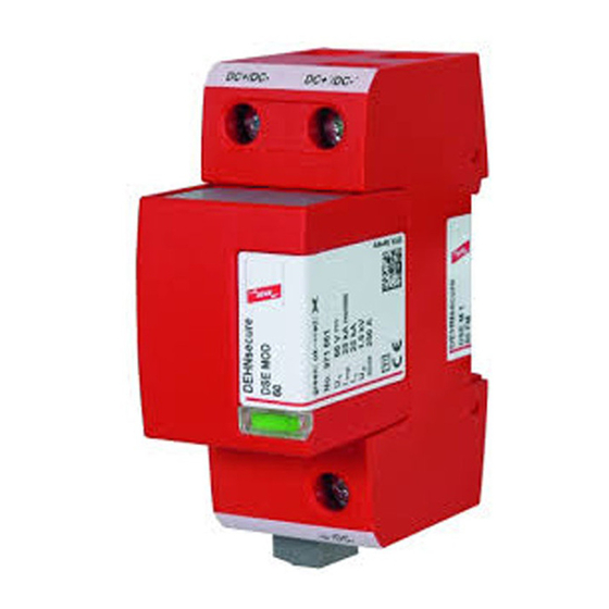
INSTALLATION INSTRUCTIONS
DG SE DC ... (FM)
Cruciform drive
(e.g.Pozidriv ® Z2)
4 Nm
3
1
2
(indoor use only / Nur im Innenraum)
Isolated systems/ Isolierte Systeme Parallel connection
F1
+
S
1
-
F2
S
2
DC+ / DC-
DC+ / DC-
DEHNguard
®
SE
DG SE DC ... (FM)
/ DC-
/ DC-
Earthing clamp / Erdungsbügel
S
min. 6 mm
2
Cu
Type EB 1 2 1.5
3
MEB
Main Earthing Busbar
Grounded systems/ Geerdete Systeme Parallel connection
F1
+
S
1
F2
S
2
DC+ / DC-
DEHNguard
®
SE
DG SE DC ... (FM)
/ DC-
S
min. 6 mm
2
Cu
3
-
SPD Type 2 Classifikation acc. EN 61643-11: ...
SPD Class II Classification acc. IEC 61643-11: ...
closed
There is no distance
from the SPD to any
earthed conductive
surface required. /
Note:
The protective covers must be closed after installation.
Es ist kein zusätzlicher
Abstand vom SPD zu
Hinweis:
geerdeten Flächen ein-
Nach der Installation müssen die Abdeckklappen
zuhalten.
geschlossen sein.
Backup Fuse / Vorsicherung
Without additional Backup Fuse / Ohne zusätzliche Vorsicherung
I k / A DC
S 1 / mm²
≤ 300
DG SE DC 60 (FM)
≤ 6
DG SE DC 242 (FM)
≤ 200
DG SE DC 550 (FM)
> 6
≤ 100
DG SE DC 900 (FM)
*) in case of earth-fault and short-circuit-proof wiring of all live conductors (DC+, DC-).
*) bei erd- und kurzschlußsicherer Verlegung aller aktiven Leiter (DC+, DC-).
I
: Max. Short-Circuit-current at point of installation /
k
I
: Max. Kurzschlußstrom am Einbauort
k
DG SE DC ... (FM)
Fuse F1
A gG
I k / A DC
> 300
25
DG SE DC 60 (FM)
DG SE DC 242 (FM)
35
35
>
> 200
DG SE DC 550 (FM)
DG SE DC 900 (FM)
Fuse F1
I k / A DC
A gPV
25
35
40
>100
50
63
80
80
>
Technical data / Technische Daten
type
module
U
(DC)
C
U
(DC)
N
I
8/20 μs
n
open
Short-circuit withstand capability I
backup fuse /
Kurzschlussfestigkeit I
I
SCCR
max.
ϑ° C
humidity / Feuchte
I
PE, DC
Ports
IP Code
L x W x H
Fuse F2
S 2 /mm²
S 3 /mm²
Fault indication / Defektanzeige
= S 1
6
keine / none
*) 6
6
keine / none
Fuse F2
S 3 /mm²
A gG
S 2 /mm²
---
4
6
---
4
6
4
6
35
Remote signalling contact / Fernmeldekontakt
Fuse F2
S 2 /mm²
A gPV
S 3 /mm²
4
6
---
4
6
---
---
4
6
4
6
---
6
6
---
6
---
6
6
6
80
Publication No. 1866 UPDATE 03.16 Mat-No. 3005578
DG SE DC 60 (FM) DG SE DC 242 (FM) DG SE DC 550 (FM) DG SE DC 900 (FM)
DG MOD E DC 60 DG MOD E DC 242
60 V
242 V
48 V
220 V
12,5 kA
without
SCCR
300 A DC
300 A DC
ohne Vorsicherung
SCCR
25 kA DC
35
-40°C ... + 80°C
5% ... 95%
<< 100 μA
IP 20 (built in / eingebaut)
104 mm 27 mm x 73 mm
min.
DC+/ DC-,
/ DC-
max.
DC+/ DC-,
/ DC-
25 mm²
11
14
12
green
test
11
14
12
green
11
14
12
red
DEHNguard
®
SE DG SE DC ... FM
U
/ I
N
N
AC:
250 V / 0,5 A
11
14
12
DC:
250 V / 0,1 A
125 V / 0,2 A
75 V / 0,5 A
max. 1,5 mm²
© COPYRIGHT 2016 DEHN + SÖHNE protected by ISO 16016
DG MOD E DC 550 DG MOD E DC 900
550 V
900 V
500 V
750 V
200 A DC
100 A DC
A gG
80 A gPV
1
12 mm
12 mm
12 mm
1,5 mm²
35 mm²
protection module
DG MOD E DC ...
ok
Remote signalling
contact
ok
replace
protection module
DG MOD E DC ...
p.t.o.
Safety
Instructions
Werbung

Verwandte Anleitungen für Dehn DG SE DC Serie


Inhaltszusammenfassung für Dehn DG SE DC Serie
- Seite 1 250 V / 0,5 A 250 V / 0,1 A 125 V / 0,2 A 75 V / 0,5 A >100 / DC- max. 1,5 mm² p.t.o. min. 6 mm Safety > © COPYRIGHT 2016 DEHN + SÖHNE protected by ISO 16016 Instructions...
- Seite 2 Publication No. 1866 / Update 03.16 Überspannungsschutz DEHN + SÖHNE Hans-Dehn-Str. 1 Tel: +49 9181 906-0 IEC 60417-6182: Blitzschutz/Erdung GmbH + Co. KG. Postfach 1640 www.dehn-international.com Installation, Arbeitsschutz 92306 Neumarkt electrotechnical expertise DEHN schützt. ® Germany Instruções de segurança Informazioni di sicurezza Indicaciones de seguridad Consignes de sécurité...