
Verwandte Anleitungen für Siemens the probe


Inhaltszusammenfassung für Siemens the probe
- Seite 1 Instruction Manual February 2008 English Deutsch Español Français the probe LEVEL TRANSMITTER Downloaded from www.Manualslib.com manuals search engine...
- Seite 2 The user is responsible for all changes and repairs made to the device by the user or the user’s agent. • All new components are to be provided by Siemens Milltronics Process Instruments Inc. • Restrict repair to faulty components only.
-
Seite 3: Installation
Installation Environmental The Probe should be mounted in an area that is within the temperature range specified and that is suitable to the housing rating and materials of construction. The front lid should be accessible to allow programming, wiring and display viewing. - Seite 4 Mounting Mount The Probe so that the face of the sensor is at least 25 cm above the highest Note: anticipated level. Threaded hinged lid 7 mm The Probe is available in three thread types: 84 mm (0.3") (3.3") max.
-
Seite 5: Operation
19 Operation Start Up program mode alphanumeric • With The Probe correctly installed (or ’20’ key aimed at a wall 0.25 to 5 m away), apply power. units • The Probe starts up displaying the ’4’... - Seite 6 • Press the key a second time to set the new distance reference. • After viewing or calibrating, Probe operation automatically reverts to the Run mode (6 sec). The calibration value is referenced from the face of The Probe sensor, in the units displayed. 4 mA calibration Press “4”...
- Seite 7 Adjustments There are several operating adjustments that can be made to The Probe. • Press the "4" and "20" keys simultaneously until the desired adjustment is obtained. A viewing sequence of the stored value is automatically initiated. • During this time, press either the "4" or "20" key to change the value. After viewing or changing, operation automatically reverts to the Run mode (6 sec).
- Seite 8 The speed of response adjustment allows the user to collectively set a number of operating parameters. is the limit to which The Probe will be able to keep up with rates of change. If The Probe measurement cannot keep up with the rate of level change, set the measurement response: adjustment from `1' to `2'.
- Seite 9 Ø = process alarm The non zero value entered becomes the alarm setpoint, referenced to The Probe's sensor face. The relay de- energizes and the contacts close when the material is hysterisis within the alarm zone. There is a hysterisis equivalent to 5% of the empty calibration distance.
- Seite 10 • When the desired option is displayed, stop pressing the key. The display will automatically return to the Run mode (6 sec). units 3 sec current option i.e. m Press “20” for option 2 i.e. ft option 2 selected 6 sec Page 8 The Probe – INSTRUCTION MANUAL 7ML19985GD61 Downloaded from www.Manualslib.com manuals search engine...
-
Seite 11: Troubleshooting
Supplement Loading vs. Supply Voltage Troubleshooting The echo is not reliable and The Probe is waiting for a valid echo before updating the measurement. Probable causes are: • material or object in contact with sensor face • The Probe is too close to the fill point •... -
Seite 12: Specifications
• Relay: 1 normally closed contact rated at 5 A at 250 V AC non-inductive or 24 V DC fault on power, application or device failure Page 10 The Probe – INSTRUCTION MANUAL 7ML19985GD61 Downloaded from www.Manualslib.com manuals search engine... - Seite 13 • Type 4X / NEMA 4X / IP65 Weight: • 1.7 Kg (3.7 lb) Approvals: • CE*, FM CSA NRTL/C * EMC performance available on request. • 3A (Sanitary model only) 7ML19985GD61 The Probe – INSTRUCTION MANUAL Page 11 Downloaded from www.Manualslib.com manuals search engine...
- Seite 14 Page 12 The Probe – INSTRUCTION MANUAL 7ML19985GD61 Downloaded from www.Manualslib.com manuals search engine...
- Seite 15 Zu störenden Einbauten (Leitern, Der Schall muss ungehindert Rohren, Verstrebungen oder und im rechten Winkel zum Schweißnähten) ist Abstand zu Flüssigkeitsspiegel gelangen halten können Sanitärer Ringbeschlag Rohr Sprossen Schweiß- nähte 7ML19985GD61 The Probe – BETRIEBSANLEITUNG Seite 1 Downloaded from www.Manualslib.com manuals search engine...
-
Seite 16: Montage
• Ziehen Sie die Einstellmutter an Gegenflansch Tank Die Innenseite des 119 mm (4.68") Hinweis: 97 mm (3.83") sanitären Tri-Clamps muss glatt und frei von Graten, Fugen oder Furchen sein. ungefähre Maße Seite 2 The Probe – BETRIEBSANLEITUNG 7ML19985GD61 Downloaded from www.Manualslib.com manuals search engine... -
Seite 17: Betrieb
Angezeigt wird der Abstand von der Sensorsendefläche zum zu messenden Füllstand in der angegebenen Einheit: • Falls eine andere Anzeige erscheint, siehe Abschnitt Betriebszustand auf Seite 4. 7ML19985GD61 The Probe – BETRIEBSANLEITUNG Seite 3 Downloaded from www.Manualslib.com manuals search engine... - Seite 18 Je nach Betriebszustand wird das Logo vollständig oder teilweise angezeigt. Zur Anzeige eines Echoverlusts (LOE) / Fehlers erscheint nach einer Wartezeit das Fragezeichen "?" neben dem Logo. Bei Empfang eines gültigen Echos erscheint das Logo 'In Ordnung'. Siehe Fehlersuche, Seite 9 . Seite 4 The Probe – BETRIEBSANLEITUNG 7ML19985GD61 Downloaded from www.Manualslib.com...
-
Seite 19: Kalibrierung, Schnelldurchlauf (Scroll)
Sie die Taste “4” um den Wert zu verringern, jeweilige Taste gedrückt halten, bis Bsp. 0,45 m der gewünschte Wert erreicht ist. Neuer Kalibrierwert 7ML19985GD61 The Probe – BETRIEBSANLEITUNG Seite 5 Downloaded from www.Manualslib.com manuals search engine... -
Seite 20: Nahbereichsausblendung
Filter Failsafe Zeit 1 m/min (3.3 ft/min) 10 min 5 m/min (16.4 ft/min) 3 min sofort 3 min 0.03 m/min (0.1 ft/min) 10 min * = Werkseinstellung Seite 6 The Probe – BETRIEBSANLEITUNG 7ML19985GD61 Downloaded from www.Manualslib.com manuals search engine... - Seite 21 Failsafe Funktionen wird sofort ausgeführt. Vorgabewert Anzeige voll Halten leer Halten Halten Halten Halten Halten p = proportionale Mess-Spanne i = umgekehrt proportionale Mess-Spanne * = Werkseinstellung 7ML19985GD61 The Probe – BETRIEBSANLEITUNG Seite 7 Downloaded from www.Manualslib.com manuals search engine...
- Seite 22 Run Modus zurück (6 Sek.). Einheit 3 Sek. Aktuelle Option, Bsp. m Taste “20” für Option 2 Bsp. ft Option 2 gewählt 6 Sek. Seite 8 The Probe – BETRIEBSANLEITUNG 7ML19985GD61 Downloaded from www.Manualslib.com manuals search engine...
-
Seite 23: Bürde / Versorgungsspannung
• U.K.: 2021748 • Frankreich: 921873 • Japan: 966217 Elektronik / Sensor: • U.S.A.: 5,267,219 5,339,292 • U.K.: 2,260,059 • Patentierte Applikationen in U.K., Kanada, Europa, Afrika, Australien 7ML19985GD61 The Probe – BETRIEBSANLEITUNG Seite 9 Downloaded from www.Manualslib.com manuals search engine... -
Seite 24: Technische Daten
Belden 8760, geschirmt, verdrilltes Paar, 28AWG (0,75 mm²) oder entsprechende Größe • Relais: 1 Öffnerkontakt mit 5 A Nennleistung bei 250 VAC, ohmsche Last oder 24 VDC Fehler bei einer Spannungs-, Applikations- oder Gerätestörung Seite 10 The Probe – BETRIEBSANLEITUNG 7ML19985GD61 Downloaded from www.Manualslib.com manuals search engine... - Seite 25 • Typ 4X / NEMA 4X / IP65 Gewicht: • 1,7 Kg (3,7 lb) Zulassungen: • CE*, FM CSA NRTL/C • * EMV Bescheinigung auf Anfrage erhältlich. • 3A (nur Sanitärausführung) 7ML19985GD61 The Probe – BETRIEBSANLEITUNG Seite 11 Downloaded from www.Manualslib.com manuals search engine...
- Seite 26 Seite 12 The Probe – BETRIEBSANLEITUNG 7ML19985GD61 Downloaded from www.Manualslib.com manuals search engine...
-
Seite 27: Instalación
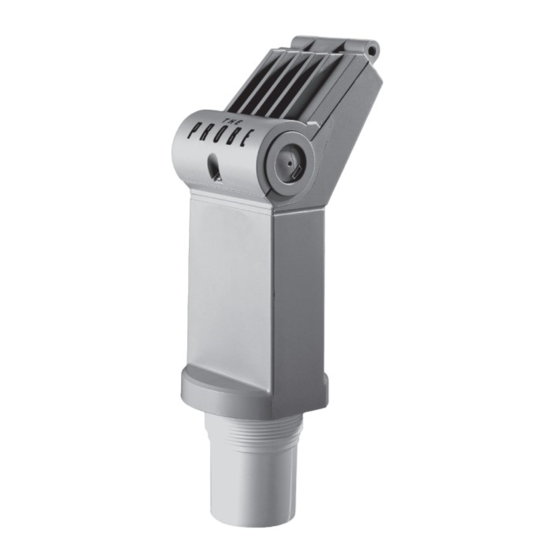
The Probe debe ser utilizado únicamente de la manera que se especifica en este manual. The Probe es un transmisor de nivel ultrasónico que combina un sensor y una parte electrónica en un cuerpo único. Está diseñado para medir niveles de líquidos en depósitos abiertos o cerrados. El sensor se fabrica en Kynar PVDF o ETFE lo que lo hace adecuado para una amplia variedad de industrias. -
Seite 28: Montaje
Montaje Montar The Probe de forma que la cara del transductor esté por lo menos 25 cm por Nota: encima del máximo nivel posible. Con rosca Tapa abatible 7 mm The Probe está disponible con tres tipos de rosca: 84 mm (0,3") -
Seite 29: Operación
A. Con la tapa cerrada, se extrae el tope de la entrada de cable situado en el lado deseado. B. Se abre la tapa aflojando su tornillo. C. Se conecta el cable a The Probe. D. Se conecta la salida mA, la alimentación eléctrica y el cableado del relé. - Seite 30 • Se puede efectuar la calibración de la distancia pulsando de nuevo la tecla correspondiente. • Después de la visualización o calibración, The Probe vuelve automáticamente al modo Run (6 segundos). El valor de calibración se calcula desde la cara del transductor, en las unidades visualizadas.
- Seite 31 Ajustes Se pueden efectuar varios ajustes para conseguir un nivel de operación óptimo de The Probe. • Pulsar simultáneamente las teclas "4" y "20" hasta visualizar el ajuste deseado. Se visualiza automáticamente el valor almacenado. • El usuario puede modificar este valor pulsando la tecla "4" ó "20". Después de la visualización o modificación, el indicador vuelve automáticamente al modo Run (6 segundos).
- Seite 32 Si dicho valor no se adapta a los cambios de nivel de material, cambiar el ajuste de Tiempo de respuesta: ‘1' a `2'. Si The Probe sigue sin responder al cambio de nivel, seleccionar la opción ‘3'. Se recomienda no seleccionar una opción que sea demasiado rápida para la aplicación.
- Seite 33 Autoprotección fallo lectura lleno mantenido vacío mantenido mantenido mantenido mantenido mantenido p = span proporcional i = span inversamente propocional * = valor de fábrica 7ML19985GD61 The Probe – MANUAL DE INSTRUCCIONES Página 7 Downloaded from www.Manualslib.com manuals search engine...
- Seite 34 • Al visualizar la opción deseada, soltar la tecla. El display / indicador vuelve automáticamente al modo Run (6 segundos). Unidades 3 seg Opción actual, ejemplo: m Pulsar “20” opción 2, ejemplo: ft Opción 2 seleccionada 6 seg Página 8 The Probe – MANUAL DE INSTRUCCIONES 7ML19985GD61 Downloaded from www.Manualslib.com manuals search engine...
-
Seite 35: Solución De Fallos
Suplemento Carga / tensión de alimentación Solución de fallos El eco no es fiable. The Probe espera un eco válido antes de actualizar la medición. Causas probables: • Material u objeto en contacto con la cara del transductor • The Probe está demasiado cerca del punto de llenado •... -
Seite 36: Especificaciones
1 contacto NC por relé, capacidad normal 5A a 250 VAC, no inductivo ó 24 VDC fallo con un paro de la alimentación eléctrica, de la aplicación o del dispositivo Página 10 The Probe – MANUAL DE INSTRUCCIONES 7ML19985GD61 Downloaded from www.Manualslib.com... - Seite 37 • 1.7 Kg (3.7 lb) Aprobaciones: • CE*, FM CSA NRTL/C * Detalle de ejecución EMC bajo pedido. • 3A (modelo para procesos sanitarios únic.) 7ML19985GD61 The Probe – MANUAL DE INSTRUCCIONES Página 11 Downloaded from www.Manualslib.com manuals search engine...
- Seite 38 Página 12 The Probe – MANUAL DE INSTRUCCIONES 7ML19985GD61 Downloaded from www.Manualslib.com manuals search engine...
-
Seite 39: Caractéristiques Environnementales
Introduction Note : • Cet instrument est conçu pour une utilisation en milieu industriel. Utilisé en zone résidentielle, cet appareil peut provoquer des perturbations des communications radio. • Le Probe doit être utilisé suivant les instructions fournies dans ce manuel. L’unité... -
Seite 40: Raccord Fileté
Montage Le Probe doit être installé de telle sorte que la face émettrice du capteur soit située au Note : moins 25 cm au dessus du niveau attendu le plus haut. Raccord fileté couvercle à charnière 7 mm L’unité est disponible en trois versions de 84 mm (0.3") (3.3") max. -
Seite 41: Mise En Service
Interconnexions • L’installation doit être effectuée par un personnel qualifié, en accord avec les Notes : dispositions locales en vigueur. • Il peut être nécessaire de séparer les câbles et conduits pour respecter les prescriptions particulières, consignes de câblage et normes électriques. A. -
Seite 42: Etats De Fonctionnement
Etalonnage L’étalonnage de la sortie analogique peut être réalisé de telle sorte qu’elle soit proportionnelle ou inversement proportionnelle au niveau mesuré. L’étalonnage des niveaux 4 et 20 mA n’est Note : pas soumis à un ordre particulier. proportionnelle inversement proportionnelle niveau haut = 20mA niveau haut = 4 mA niveau bas = 4 mA... - Seite 43 Réglages Plusieurs réglages sont possibles pour optimiser le fonctionnement de l’unité Probe. • Presser les touches "4" et "20" jusqu’à obtenir le réglage souhaité. La valeur programmée est automatiquement affichée. • Pendant ce temps, la valeur peut être modifiée en pressant la touche "4" ou "20". Une fois la valeur visualisée ou modifiée, l’unité...
-
Seite 44: Temps De Réponse
Zone Morte La zone morte est utilisée pour masquer la zone sous le Le Probe capteur où les échos parasites sont à des niveaux zone morte pouvant interférer avec le traitement de l’écho vrai. La zone morte est mesurée vers l’extérieur à partir de la face du capteur. - Seite 45 • Pour modifier le temps de réponse, visualiser `SP'. • Presser la touche "20" pour visualiser les options (1-2-3). Presser la touche "4" pour visualiser les options (3-2-1). • Une fois l’option souhaitée affichée, cesser de presser la touche. L’afficheur revient automatiquement en mode Run (6 secondes).
- Seite 46 • Pour modifier la valeur par défaut, visualiser `FLS'. • Presser la touche "20" pour visualiser les options (1-2-3). Presser la touche "4" pour revenir aux options (3-2-1). • Cesser de presser la touche dès que l’option souhaitée est affichée. L’affichage revient automatiquement en mode Run (6 secondes).
-
Seite 47: Dépistage Des Défauts
Supplément Charge / tension d’alimentation Dépistage des défauts L’écho reçu n’est pas fiable. Le Probe attend de recevoir un écho valide avant de rafraîchir la mesure. Les causes probables sont : • Matériau ou cible en contact avec la face émettrice du capteur •... -
Seite 48: Caractéristiques Techniques
Caractéristiques Techniques Alimentation : • 18 à 30 V cc, 0.2 A maximum Caractéristiques environnementales : • montage : en intérieur / extérieur • altitude : 2000 m maximum • température continue : - 40 à +60°C (-40 à +140°F) ambiante: -20°C (-5°F) pour montage métallique •... - Seite 49 Construction : • monobloc, incluant le capteur et l’électronique • corps du capteur : matériau : PVDF ou ETFE montage : filetage : 2”NPT, 2" BSP PF2 bride : adaptateur bride, 3" ANSI, DIN 65PN10 et JIS 10K3B sanitaire : col sanitaire 4" approuvé par la FDA avec anneau d’étanchéité...
- Seite 50 Page 12 Le Probe – MANUEL D’INSTRUCTIONS 7ML19985GD61 Downloaded from www.Manualslib.com manuals search engine...
- Seite 51 Siemens Milltronics Process Instruments Inc. Siemens Milltronics Process Instruments Inc. 2008 1954Technology Drive, P .O. Box 4225 Subject to change without prior notice Peterborough, ON, Canada K9J 7B1 Rev. 1.0 Tel: (705) 745-2431 Fax: (705) 741-0466 *7ml19985GD61* Email: techpubs.smpi@siemens.com...