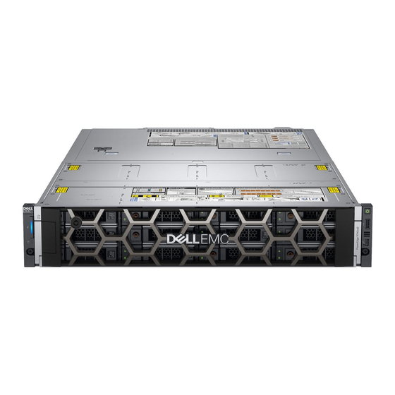
Dell EMC PowerEdge R740xd2 Installations- Und Servicehandbuch
Vorschau ausblenden
Andere Handbücher für EMC PowerEdge R740xd2:
- Technische spezifikation (26 Seiten) ,
- Installations- und servicehandbuch (184 Seiten) ,
- Installations- und servicehandbuch (151 Seiten)

Verwandte Anleitungen für Dell EMC PowerEdge R740xd2


Inhaltszusammenfassung für Dell EMC PowerEdge R740xd2
- Seite 1 Dell EMC PowerEdge R740xd2 Installations- und Service-Handbuch Vorschriftenmodell: E56S Series Vorschriftentyp: E56S001...
- Seite 2 Mit WARNUNG wird auf eine potenziell gefährliche Situation hingewiesen, die zu Sachschäden, Verletzungen oder zum Tod führen kann. © 2018 – 2019 Dell Inc. oder Ihre Tochtergesellschaften. Alle Rechte vorbehalten. Dell, EMC und andere Marken sind Marken von Dell Inc. oder entsprechenden Tochtergesellschaften. Andere Marken können Marken ihrer jeweiligen Inhaber sein.
-
Seite 3: Inhaltsverzeichnis
Inhaltsverzeichnis 1 Über dieses Dokument........................8 2 Dell EMC PowerEdge R740xd2 System overview................9 Front view of the system..............................9 Control panels................................. 10 Rear view of the system..............................11 Inside the system..................................13 Ausfindigmachen des Informationsschilds Ihres Systems....................14 System Information Label..............................16 3 Anfängliche Systemeinrichtung und Erstkonfiguration..............19... - Seite 4 System cover..................................49 Removing the system cover............................49 Installing the system cover............................50 Air shroud....................................51 Removing the air shroud............................... 51 Installing the air shroud..............................53 Internal PERC riser................................54 Removing the internal PERC riser..........................54 Installing the internal PERC riser..........................56 Removing the PERC card from the internal PERC riser..................
- Seite 5 Cable routing..................................90 System memory................................... 91 Richtlinien für Systemspeicher............................. 91 Allgemeine Richtlinien zur Installation von Speichermodulen...................92 Betriebsartspezifische Richtlinien..........................93 Removing a memory module............................96 Installing a memory module............................97 Processor and heat sink..............................98 Removing a processor and heat sink module......................98 Removing the processor ..............................99 Installing the processor..............................
- Seite 6 Upgrading the Trusted Platform Module........................144 Initializing TPM for BitLocker users........................... 146 Initialisieren des TPM 1.2 für TXT-Benutzer......................146 Initializing the TPM 2.0 for TXT users........................146 Cable chain assembly.................................147 Removing cable chain assembly..........................147 Installing the cable chain assembly..........................150 Control panel..................................
- Seite 7 9 Wie Sie Hilfe bekommen......................178 Recycling or End-of-Life service information.........................178 Contacting Dell................................... 178 Accessing system information by using QRL......................... 178 Quick Resource Locator for Dell EMC PowerEdge R740xd2 System..............179 Receiving automated support with SupportAssist ....................... 179 10 Documentation resources......................180 Inhaltsverzeichnis...
-
Seite 8: Über Dieses Dokument
Über dieses Dokument Mit diesem Dokument erhalten Sie eine Übersicht über das System, Informationen zur Installation und dem Austausch von Komponenten, technische Daten, diagnostische Mittel sowie Richtlinien zur Installation bestimmter Komponenten. Über dieses Dokument... -
Seite 9: Dell Emc Poweredge R740Xd2 System Overview
Dell EMC PowerEdge R740xd2 System overview The Dell EMC PowerEdge R740xd2 System is a 2U rack server that supports up to: • Two Intel Xeon Scalable Processor • 16 DIMM slots • Two redundant power supply units • 26 SAS, SATA, Nearline SAS hard drives or SSDs... -
Seite 10: Control Panels
Abbildung 3. Right control panel view 1. Power button 2. USB 2.0-compliant port 3. Micro USB 2.0-compliant port for iDRAC Direct 4. iDRAC LED indicator ANMERKUNG: For more information on the ports, see the ports and connectors specifications section. Dell EMC PowerEdge R740xd2 System overview... -
Seite 11: Rear View Of The System
1. Serial port 2. Drive (2) 3. Full-height riser slot (slot 2) 4. Power supply unit (PSU 1) 5. Information tag 6. Power supply unit (PSU 2) 7. LOM ethernet port (2) 8. Ethernet port (Gb1) Dell EMC PowerEdge R740xd2 System overview... - Seite 12 16. System identification button Abbildung 7. Back panel features of system without risers 1. Serial port 2. Low-profile PCIe expansion card (slot 4) 3. Low-profile PCIe expansion card (slot 5) 4. Low-profile PCIe expansion card (slot 6) Dell EMC PowerEdge R740xd2 System overview...
-
Seite 13: Inside The System
2. Drive bay 2 3. Fans (6) 4. Memory module 5. Processor and heatsink module 1 6. Processor and heatsink module 2 7. System board 8. LOM riser card 9. Internal PERC riser 10. Air shroud Dell EMC PowerEdge R740xd2 System overview... -
Seite 14: Ausfindigmachen Des Informationsschilds Ihres Systems
Alternativ finden Sie die Informationen unter Umständen auf einem Aufkleber auf dem Gehäuse des Systems. Alternativ können sich diese Informationen auch auf dem als Mini-Enterprise-Service-Tag (MEST) bezeichneten Etikett auf dem Gehäuse an der Rückseite des Systems befinden. Mithilfe dieser Informationen kann Dell Support-Anrufe an den richtigen Mitarbeiter weiterleiten. Dell EMC PowerEdge R740xd2 System overview... - Seite 15 Abbildung 10. Ausfindigmachen des Informationsschilds Ihres Systems 1. Informationschild (Draufsicht) 2. Etikett mit iDRAC-MAC-Adresse und Kennwort für den sicheren iDRAC-Zugriff 3. Express-Servicecode 4. QRL-Etikett 5. Informationsschild (Rückansicht) Dell EMC PowerEdge R740xd2 System overview...
-
Seite 16: System Information Label
System Information Label Abbildung 11. PowerEdge R740xd2 – Service information Dell EMC PowerEdge R740xd2 System overview... - Seite 17 Abbildung 12. Memory information Abbildung 13. OCP installation Abbildung 14. Riser installation Abbildung 15. Rear drive cage installation Dell EMC PowerEdge R740xd2 System overview...
- Seite 18 Abbildung 16. Drive Bays Operation Abbildung 17. Drive configuration and layout Abbildung 18. System LED indicator and Express Service Tag Dell EMC PowerEdge R740xd2 System overview...
-
Seite 19: Anfängliche Systemeinrichtung Und Erstkonfiguration
For more information about setting up your system, see the Getting Started Guide that shipped with your system. iDRAC configuration The Integrated Dell Remote Access Controller (iDRAC) is designed to make system administrators more productive and improve the overall availability of Dell systems. iDRAC alerts administrators about system issues and enables them to perform remote system management. -
Seite 20: Log In To Idrac
The license files are enabled on the sleds through iDRAC. For more information about drivers, documentation, and white papers on the Intel QAT, see https://01.org/intel-quickassist-technology. For more information about logging in to the iDRAC and iDRAC licenses, see the latest Integrated Dell Remote Access Controller User's Guide at www.dell.com/poweredgemanuals. -
Seite 21: Downloading Drivers And Firmware
Verwendung von virtuellen iDRAC-Medien www.dell.com/idracmanuals Downloading drivers and firmware Dell EMC recommends that you download and install the latest BIOS, drivers, and systems management firmware on your system. Voraussetzungen Ensure that you clear the web browser cache before downloading the drivers and firmware. -
Seite 22: Pre-Operating System Management Applications
You can manage basic settings and features of a system without booting to the operating system by using the system firmware. Themen: • Optionen zum Verwalten der Vor-Betriebssystemanwendungen • System Setup • Dell Lifecycle Controller • Start-Manager • PXE-Boot Optionen zum Verwalten der Vor- Betriebssystemanwendungen Im System sind die folgenden Optionen zum Verwalten der Vor-Betriebssystemanwendungen enthalten: •... -
Seite 23: System Bios
The iDRAC settings utility is an interface to set up and configure the iDRAC parameters by using UEFI (Unified Extensible Firmware Interface). You can enable or disable various iDRAC parameters by using the iDRAC settings utility. For more information about this utility, see Integrated Dell Remote Access Controller User’s Guide at www.dell.com/poweredgemanuals. -
Seite 24: System Information
Option Description Serial Specifies options to manage the serial ports, its related features and options. Communication System Profile Specifies options to change the processor power management settings, memory frequency. Settings System Security Specifies options to configure the system security settings, such as System password, setup password, Trusted Platform Module (TPM) security, and UEFI secure boot. -
Seite 25: Anzeigen Der "Memory Settings" (Speichereinstellungen)
Option Description System CPLD Specifies the current version of the System complex programmable logic device (CPLD) firmware. Version UEFI Compliance Specifies the UEFI compliance level of the System firmware. Version Speichereinstellungen Sie können den Bildschirm Memory Settings (Speichereinstellungen) verwenden, um sämtliche Speichereinstellungen anzuzeigen und spezielle Speicherfunktionen wie Systemspeichertests und Knoten-Interleaving zu aktivieren oder zu deaktivieren. -
Seite 26: Prozessoreinstellungen
Option Beschreibung Knoten- Gibt an, ob Non-Uniform Memory Architecture (NUMA) unterstützt wird. Wenn dieses Feld auf Enabled Interleaving (Aktiviert) eingestellt ist, wird Speicher-Interleaving unterstützt, falls eine symmetrische Speicherkonfiguration installiert wird. Wenn die Option auf Disabled (Deaktiviert) eingestellt ist, unterstützt das System asymmetrische Speicherkonfigurationen (NUMA). -
Seite 27: Beschreibung
Option Beschreibung Um eine optimale Leistung zu gewährleisten, sollten Sie wählen Sie Maximale Datenrate. Jede Verringerung in der Kommunikation Verbindungsfrequenz wirkt sich auf die Leistung von nicht-lokale Speicherzugriffe und Cache- Datenkonsistenz übergreifend Datenverkehr. Darüber hinaus können langsamer Zugriff auf nicht-lokale E/A- Geräte von einer bestimmten CPU. -
Seite 28: Detail Zu "Sata Settings" (Sata-Einstellungen)
Option Beschreibung Option Beschreibung Level 2 Cache Gibt die Gesamtgröße des L2-Caches an. (Level 2-Cache) Level 3 Cache Gibt die Gesamtgröße des L3-Caches an. (Level 3-Cache) Anzahl der Kerne Gibt die Anzahl der aktivierten Kerne je Prozessor an. Maximum Memory Gib die maximale Speicherkapazität pro Prozessor an. -
Seite 29: Details Zu "Boot Settings" (Starteinstellungen)
Option Beschreibung Option Beschreibung Drive Type Gibt den Typ des Laufwerks an, das am SATA-Anschluss angeschlossen ist. (Laufwerkstyp) Kapazität Gibt die Gesamtkapazität des Laufwerks an. Für Geräte mit Wechselmedien, wie z. B. für optische Laufwerke, ist dieses Feld nicht definiert. Boot Settings You can use the Boot Settings screen to set the boot mode to either BIOS or UEFI. - Seite 30 UEFI and can only be installed from the BIOS boot mode. ANMERKUNG: For the latest information about supported operating systems, go to www.dell.com/ossupport Changing boot order Info über diese Aufgabe You may have to change the boot order if you want to boot from a USB key or an optical drive. The following instructions may vary if you have selected BIOS for Boot Mode.
-
Seite 31: Details Zum Bildschirm "Network Settings" (Netzwerkeinstellungen)
2. Use the arrow keys to select a boot device, and use the plus (+) and minus (-) sign keys to move the device down or up in the order. 3. Click Exit, and then click Yes to save the settings on exit. Network Settings You can use the Network Settings screen to modify UEFI PXE, iSCSI, and HTTP boot settings. -
Seite 32: Details Zu "Integrated Devices" (Integrierte Geräte)
Option Beschreibung Option Beschreibung VLAN-Priorität Dieser Wert ist auf 0 eingestellt. URI (wird vom DHCP-Server erfragt, wenn nicht festgelegt) UEFI-iSCSI- Ermöglicht die Steuerung der iSCSI-Gerätekonfiguration. Einstellungen Tabelle 4. Details zum Bildschirm „UEFI iSCSI Settings“ (UEFI ISCSI-Einstellungen) Option Beschreibung iSCSI-Initiator-Name Legt den Namen des iSCSI-Initiators im IQN-Format fest. - Seite 33 Option Beschreibung User Accessible Legt die benutzerzugängliche USB-Schnittstellen fest. Durch die Auswahl der Option Only Back Ports On (Nur USB Ports hintere Anschlüsse aktiviert) werden die vorderen USB-Anschlüsse deaktiviert und durch die Auswahl von All Ports Off (Alle Anschlüsse deaktiviert) werden sowohl die vorderen als auch die hinteren USB-Anschlüsse deaktiviert.
-
Seite 34: Pre-Operating System Management Applications
Option Beschreibung Wenn die Option „Internal SD Card Redundancy“ (Redundanz für interne SD-Karten) auf Disabled (Deaktiviert) eingestellt ist, ist nur die primäre MicroSD-Karte für das Betriebssystem sichtbar. Diese Option ist standardmäßig auf Disabled (Deaktiviert) eingestellt. Internal microSD Wenn Redundancy (Redundanz) auf Disabled (Deaktiviert) eingestellt ist, kann eine der MicroSD-Karten Primary Card ausgewählt werden, um als Massenspeichergerät zu fungieren, indem sie als primäre Karte festgelegt wird. -
Seite 35: Serielle Kommunikation
Option Beschreibung Slot Bifurcation Ermöglicht Platform Default Bifurcation (Standardverzweigung für Plattform), Auto discovery of Bifurcation (Automatische Ermittlung von Verzweigungen) und Manual bifurcation Control (Manuelle Steuerung von Verzweigungen). Die Standardeinstellung auf Platform Standard Bifurkation. Auf das Feld für Steckplatz-Verzweigung kann zugegriffen werden, wenn Manual bifurcation Control (Manuelle Steuerung von Verzweigungen) eingestellt ist. -
Seite 36: Systemprofileinstellungen
Option Description Serial Port Enables you to set the port address for serial devices. This field sets the serial port address to either COM1 or Address COM2 (COM1=0x3F8, COM2=0x2F8). This option is set to Serial Device1=COM2 or Serial Device 2=COM1 by default. -
Seite 37: Systemsicherheit
You can only change the rest of the options if the mode is set to Custom.This option is set to Performance Per Watt Optimized (DAPC) by default. DAPC is Dell Active Power Controller. Other options include Performance Per Watt (OS), Performance, and Workstation Performance. - Seite 38 Viewing System Security To view the System Security screen, perform the following steps: Schritte 1. Power on, or restart your System. 2. Press F2 immediately after you see the following message: F2 = System Setup ANMERKUNG: If your operating system begins to load before you press F2, wait for the System to finish booting, and then restart your System and try again.
- Seite 39 Option Beschreibung TPM- Ermöglicht das Ändern des TPM-Betriebszustands. Diese Option ist standardmäßig auf Informationen Enable (Aktivieren) eingestellt. TPM Firmware Zeigt die TPM-Firmware-Version an. TPM Hierarchy Dient zum Aktivieren, Deaktivieren oder Löschen von Speicher- und Endorsement Key- Hierarchien. Wenn diese Einstellung auf Enabled (Aktiviert) festgelegt ist, können die Speicher- und Endorsement Key-Hierarchien verwendet werden.
- Seite 40 Option Beschreibung auf Custom (Benutzerdefiniert) eingestellt ist, verwendet das BIOS benutzerdefinierte Schlüssel und Zertifikate. Die Richtlinie für den sicheren Start ist standardmäßig auf Standard festgelegt. Secure Boot Mode Legt fest, wie das BIOS die Regel für sicheren Start Objekte (PK, KEK, db, dbx). Wenn der aktuelle Modus eingestellt ist zum Modus "Bereitgestellt, die verfügbaren Optionen sind Benutzermodus und Modus "Bereitgestellt.
-
Seite 41: Betrieb Mit Aktiviertem Setup-Kennwort
6. In the Setup Password field, type your setup password and press Enter or Tab. A message prompts you to reenter the setup password. 7. Reenter the setup password, and click OK. 8. Press Esc to return to the System BIOS screen. Press Esc again. A message prompts you to save the changes. - Seite 42 Wird auch beim dritten Versuch nicht das korrekte Passwort eingegeben, zeigt das System die folgende Meldung an: Password Invalid. Number of unsuccessful password attempts: <x> Maximum number of password attempts exceeded.System halted. Number of unsuccessful password attempts: <3> Maximum number of password attempts exceeded. System Halted! Auch nach dem Herunterfahren und Neustarten des System wird die Fehlermeldung angezeigt, bis das korrekte Kennwort eingegeben wurde.
-
Seite 43: Verschiedene Einstellungen
UEFI boot mode. You cannot set the option to Enabled if UEFI Secure Boot mode is enabled. This option is set to Disabled by default. Dell Wyse Enables or disables the Dell Wyse P25/P45 BIOS Access. This option is set to Enabled by default. P25/P45 BIOS Access Power Cycle Enables or disables the Power Cycle Request. -
Seite 44: Idrac Settings Utility
Extensible Firmware Interface) -Anwendungen. Embedded system management The Dell Lifecycle Controller provides advanced embedded system management throughout the lifecycle of the system. The Dell Lifecycle Controller can be started during the boot sequence and can function independently of the operating system. -
Seite 45: Hauptmenü Des Start-Managers
Startmenü Launch System Ermöglicht den Zugriff auf das System-Setup. Setup (System- Setup starten) Launch Lifecycle Beendet den Start-Manager und ruft das Dell Lifecycle Controller-Programm auf. Controller (Starten des Lifecycle Controller) Systemdienstprog Zum Starten von Systemdienstprogrammen wie die Systemdiagnose und UEFI-Shell. -
Seite 46: Installing And Removing System Components
Produktdokumentation genehmigt ist, oder wenn Sie vom Team des Online- oder Telefonsupports dazu aufgefordert werden. Schäden durch nicht von Dell genehmigte Wartungsarbeiten werden durch die Garantie nicht abgedeckt. Lesen und beachten Sie die Sicherheitshinweise, die Sie zusammen mit Ihrem Produkt erhalten haben. -
Seite 47: Recommended Tools
Schritte 1. Reconnect the peripherals and connect the System to the electrical outlet. 2. Power on the attached peripherals and then power on the System. Recommended tools You need the following tools to perform the removal and installation procedures: • Key to the bezel lock The key is required only if your system includes a bezel. -
Seite 48: Installing The Front Bezel
Abbildung 19. Removing the front bezel Nächste Schritte Replace the front bezel. Installing the front bezel Voraussetzungen 1. Follow the safety guidelines listed in Safety instruction. 2. Locate and remove the bezel key. ANMERKUNG: The bezel key is part of the front bezel package. Schritte 1. -
Seite 49: System Cover
6. Remove the system from the rack and place it on an ESD work bench. For more information, see the Rail Installation Guide at www.dell.com/poweredgemanuals. Schritte 1. Using a 1/4-inch flat head or Phillips #2 screwdriver, turn the lock counterclockwise to the unlock position. -
Seite 50: Installing The System Cover
7. Remove the system from the rack and place it on an ESD work bench. For more information, see the Schieneninstallationshandbuch unter www.dell.com/poweredgemanuals. Schritte 1. Align the tabs on the system cover with the guide slots on the system. -
Seite 51: Air Shroud
5. Remove the power supply units. 6. Remove the system from the rack and place it on an ESD work bench. For more information, see the Schieneninstallationshandbuch unter www.dell.com/poweredgemanuals. Remove the system cover. 8. If installed, remove the butterfly riser. - Seite 52 Abbildung 23. Removing air shroud Abbildung 24. Removing air shroud for system with rear drive configuration Nächste Schritte Replace the air shroud. Installing and removing system components...
-
Seite 53: Installing The Air Shroud
6. Remove the power supply units. 7. Remove the system from the rack and place it on an ESD work bench. For more information, see the Schieneninstallationshandbuch unter www.dell.com/poweredgemanuals. Remove the system cover. 9. If installed, remove the butterfly riser. -
Seite 54: Internal Perc Riser
5. Remove the power supply units. 6. Remove the system from the rack and place it on an ESD work bench. For more information, see the Schieneninstallationshandbuch unter www.dell.com/poweredgemanuals. Remove the system cover. Remove the air shroud. - Seite 55 Abbildung 27. Removing internal PERC riser 2. Turn over the internal riser so that the PERC card is facing up. 3. Using a Phillips #2 screwdriver, loosen the screws from the cable connector and disconnect the cable connected to the internal PERC card.
-
Seite 56: Installing The Internal Perc Riser
6. Remove the power supply units. 7. Remove the system from the rack and place it on an ESD work bench. For more information, see the Schieneninstallationshandbuch unter www.dell.com/poweredgemanuals. Remove the system cover. Remove the air shroud. -
Seite 57: Removing The Perc Card From The Internal Perc Riser
5. Remove the power supply units. 6. Remove the system from the rack and place it on an ESD work bench. For more information, see the Schieneninstallationshandbuch unter www.dell.com/poweredgemanuals. Remove the system cover. Remove the air shroud. 9. If installed, remove the rear drive cage. -
Seite 58: Installing Perc Card Into The Internal Perc Riser
6. Remove the power supply units. 7. Remove the system from the rack and place it on an ESD work bench. For more information, see the Schieneninstallationshandbuch unter www.dell.com/poweredgemanuals. Remove the system cover. Remove the air shroud. 10. If installed, remove the rear drive cage. -
Seite 59: Cooling Fans
5. Remove the power supply units. 6. Remove the system from the rack and place it on an ESD work bench. For more information, see the Schieneninstallationshandbuch unter www.dell.com/poweredgemanuals. Remove the system cover. Installing and removing system components... - Seite 60 Remove the air shroud. Remove the internal PERC riser. 10. Move the cables out of the way to access the cooling fan cable connector on the system board. Schritte 1. Press the tabs on the fan cable connector and disconnect the cable from the system board. 2.
-
Seite 61: Installing Cooling Fan
6. Remove the power supply units. 7. Remove the system from the rack and place it on an ESD work bench. For more information, see the Schieneninstallationshandbuch unter www.dell.com/poweredgemanuals. Remove the system cover. Remove the air shroud. - Seite 62 Abbildung 35. Installing cooling fan Abbildung 36. Connecting fan 1 cable to PIB connector Nächste Schritte Install the internal PERC riser. Install the air shroud. 3. Install the system cover. Installing and removing system components...
-
Seite 63: Intrusion Switch
5. Remove the power supply units. 6. Remove the system from the rack and place it on an ESD work bench. For more information, see the Schieneninstallationshandbuch unter www.dell.com/poweredgemanuals. Remove the system cover. Remove the air shroud. Remove the internal PERC riser. -
Seite 64: Installing The Intrusion Switch
6. Remove the power supply units. 7. Remove the system from the rack and place it on an ESD work bench. For more information, see the Schieneninstallationshandbuch unter www.dell.com/poweredgemanuals. Remove the system cover. Remove the air shroud. Remove the internal PERC riser. -
Seite 65: Drive Bay
Drive bay Opening the drive bays Voraussetzungen VORSICHT: Drive bays should not be in service position for more than 5 minutes because of thermal concerns. When the drive bay is open for more than five minutes, the cooling fans spin at a higher speed to provide extra cooling to the system. -
Seite 66: Drives
Schritte 1. Pull back the blue release tabs on both sides and slide the drive bays into the system, until both the bays lock into place. Abbildung 40. Closing drive bays 2. If required, lock the drive bay lock located above left release latch, by pushing it down. Nächste Schritte If removed, install front bezel. -
Seite 67: Installing A Drive Blank
Abbildung 41. Removing a drive blank Nächste Schritte Replace a drive blank. Installing a drive blank Voraussetzungen 1. Follow the safety guidelines listed in Safety instructions. 2. If installed, remove the front bezel. VORSICHT: To maintain proper system cooling, drive blanks must be installed in all empty drive slots. VORSICHT: Mixing drive blanks from previous generations of PowerEdge servers is not supported. -
Seite 68: Entfernen Des Laufwerks Aus Dem Laufwerkträger
VORSICHT: Before attempting to remove or install a drive while the system is running, see the documentation for the storage controller card to ensure that the host adapter is configured correctly to support drive removal and insertion. VORSICHT: Mixing drives from previous generations of PowerEdge servers is not supported. VORSICHT: To prevent data loss, ensure that your operating system supports drive installation. -
Seite 69: Installing A Drive Carrier
Abbildung 44. Entfernen des Laufwerks aus dem Laufwerkträger Nächste Schritte Setzen Sie gegebenenfalls ein Laufwerk in den Laufwerkträger ein. Installing a drive carrier Voraussetzungen VORSICHT: Before attempting to remove or install a drive while the system is running, see the documentation for the storage controller card to ensure that the host adapter is configured correctly to support drive removal and insertion. -
Seite 70: Einsetzen Eines Laufwerks In Den Laufwerkträger
Abbildung 45. Installing a drive carrier Nächste Schritte If removed, install the front bezel. Einsetzen eines Laufwerks in den Laufwerkträger Voraussetzungen VORSICHT: Das Kombinieren von Laufwerkträgern aus anderen Generationen von PowerEdge-Servern wird nicht unterstützt. ANMERKUNG: Stellen Sie beim Einsetzen eines Laufwerks in den Laufwerkträger sicher, dass die Schrauben mit einem Anzugsmoment von (4 Pfund-Zoll) angezogen werden. -
Seite 71: Removing A 2.5-Inch Drive From A 3.5-Inch Drive Adapter
Abbildung 46. Einsetzen eines Laufwerks in den Laufwerkträger Nächste Schritte Installieren Sie den Laufwerkträger. Removing a 2.5-inch drive from a 3.5-inch drive adapter Voraussetzungen ANMERKUNG: A 2.5-inch drive is installed in a 3.5-inch drive adapter, which is then installed in the 3.5-inch drive carrier. -
Seite 72: Installing A 2.5-Inch Drive Into A 3.5-Inch Drive Adapter
Abbildung 47. Removing a 2.5 inch drive from a 3.5-inch drive adapter Nächste Schritte Replace a 2.5-inch drive into a 3.5-inch drive adapter. Installing a 2.5-inch drive into a 3.5-inch drive adapter Voraussetzungen 1. Follow the safety guidelines listed in Safety instructions Remove the drive carrier. -
Seite 73: Removing A 3.5-Inch Drive Adapter From A 3.5-Inch Drive Carrier
Abbildung 48. Installing a 2.5-inch drive into a 3.5-inch drive adapter Removing a 3.5-inch drive adapter from a 3.5-inch drive carrier Voraussetzungen 1. Follow the safety guidelines listed in Safety instructions. Schritte 1. Using a Phillips #1 screwdriver, remove the screws from the rails on the drive carrier. 2. -
Seite 74: Installing A 3.5-Inch Drive Adapter Into The 3.5-Inch Drive Carrier
Nächste Schritte Install the 3.5-inch drive adapter into the 3.5-inch drive carrier. Installing a 3.5-inch drive adapter into the 3.5-inch drive carrier Voraussetzungen 1. Follow the safety guidelines listed in Safety instructions. Install the 2.5-inch drive into the 3.5-inch drive adapter. -
Seite 75: Installing The Drive Bay 1 Backplane Bracket
Open the drive bays. Schritte 1. Using a Phillips #1 screwdriver, remove the screws on top of the drive bay 1. 2. Slide the bracket to the right to disengage it from the slots at the bay base in drive bay 1. 3. -
Seite 76: Removing The Drive Bay 2 Backplane Brackets
7. Remove the system from the rack and place it on an ESD work bench. For more information, see the Schieneninstallationshandbuch unter www.dell.com/poweredgemanuals. Open the drive bays. Schritte 1. Using a Phillips #1 screwdriver, remove the screws on the top of the drive bay 2, securing the backplane brackets. -
Seite 77: Installing The Drive Bay 2 Backplane Brackets
8. Remove the system from the rack and place it on an ESD work bench. For more information, see the Schieneninstallationshandbuch unter www.dell.com/poweredgemanuals. Open the drive bays. Schritte 1. Align the backplane brackets with the slots at the bay base in drive bay 2. -
Seite 78: Bay Intrusion Switch
Abbildung 54. Installing bay 2 backplane brackets Nächste Schritte 1. Place the system into the rack. For more information, see the Schieneninstallationshandbuch unter www.dell.com/ poweredgemanuals. Open the drive bays, install drives, and then close the drive bays. 3. Install the power supply units. -
Seite 79: Installing Bay Intrusion Switch
Abbildung 55. Removing the bay intrusion switch Nächste Schritte Replace the bay intrusion switch. Installing bay intrusion switch Voraussetzungen 1. Follow the safety guidelines listed in Safety instructions. 2. Follow the procedure listed in Before working inside your system. 3. If installed, remove the front bezel. -
Seite 80: Rear Drive Cage
5. Remove the power supply units. 6. Remove the system from the rack and place it on an ESD work bench. For more information, see the Schieneninstallationshandbuch unter www.dell.com/poweredgemanuals. Remove the system cover. Remove the air shroud. -
Seite 81: Installing The Rear Drive Cage
6. Remove the power supply units. 7. Remove the system from the rack and place it on an ESD work bench. For more information, see the Schieneninstallationshandbuch unter www.dell.com/poweredgemanuals. Remove the system cover. Remove the air shroud. Remove all the rear drives. -
Seite 82: Drive Backplane
Install the air shroud. 4. Install the system cover. 5. Place the system into the rack. For more information, see the Schieneninstallationshandbuch unter www.dell.com/poweredgemanuals Open the drive bays, install drives, and then close the drive bays. 7. Install the power supply units. -
Seite 83: Removing The Drive Bay 1 Backplane
Abbildung 59. Rückwandplatine für zwölf 3,5-Zoll-Laufwerke 1. Netzanschluss (J_BP_PWR1) 2. SAS/SATA-Kabelanschluss (BP SAS A1) 3. SAS/SATA-Kabelanschluss (BP SAS A2) 4. Signalanschluss(J_BP_SIG1) 5. SAS/SATA-Kabelanschluss (BP SAS B0) 6. SAS/SATA-Kabelanschluss (BP SAS A0) 7. Anschluss für Eingriffsschalterkabel Abbildung 60. Rückwandplatine für zwei 3,5-Zoll-Laufwerke (hinten) 1. -
Seite 84: Installing The Drive Bay 1 Backplane
Remove the bay intrusion switch. 8. Disconnect all the cables from the backplane. Schritte 1. Using Phillips #2 screwdriver, remove all the screws securing the backplane. Abbildung 61. Removing the screws from the backplane 2. Hold the backplane by the edges and remove it from the bay. Abbildung 62. -
Seite 85: Removing The Drive Bay 2 Backplane
2. If installed, remove front bezel. Remove all the drives from the drive slots from bay 1. Open the drive bays. Remove the drive bay 1 bracket. Remove the bay intrusion switch. 7. Disconnect all the cables from the backplane. Schritte 1. - Seite 86 6. Remove the system from the rack and place it on an ESD work bench. For more information, see the Schieneninstallationshandbuch unter www.dell.com/poweredgemanuals. Open the drive bays. ANMERKUNG: Ensure that the drive bay is fully open to access the backplane.
-
Seite 87: Installing The Drive Bay 2 Backplane
7. Remove the power supply units. 8. Remove the system from the rack and place it on an ESD work bench. For more information, see the Schieneninstallationshandbuch unter www.dell.com/poweredgemanuals. Open the drive bays. Remove the drive bay 2 brackets. 11. Disconnect all the cables from the backplane. -
Seite 88: Removing The Rear Drive Backplane
6. Remove the system from the rack and place it on an ESD work bench. For more information, see the Schieneninstallationshandbuch unter www.dell.com/poweredgemanuals. Remove the drives from the rear drive cage. 8. Disconnect all the cables from the backplane. -
Seite 89: Installing The Rear Drive Backplane
Install the drives into the rear drive cage. 3. Connect all the cables to the backplane. 4. Place the system into the rack. for more information, see the Schieneninstallationshandbuch unter www.dell.com/poweredgemanuals. Open the drive bays, install drives, and then close the drive bays. -
Seite 90: Cable Routing
Cable routing Tabelle 8. Cable routing legend Color Description Power Green Signal Grey Data Abbildung 69. Cable routing - System with 2 x 3.5-inch rear drive backplane connected to cable chain assembly Abbildung 70. Cable routing - System with 2 x 3.5-inch rear drive backplane connected to riser PERC Installing and removing system components... -
Seite 91: System Memory
Abbildung 71. Cable routing - System with 2 x 3.5-inch rear drive backplane connected to system board SATA port System memory Richtlinien für Systemspeicher PowerEdge-Systeme unterstützen DDR4-registrierte DIMMs (RDIMMs). Systemspeicher enthält Anweisungen, die ausgeführt von den Prozessor. Das System enthält 16 Speichersockel. Prozessor1 unterstützt bis zu 10 Speichersockel und Prozessor2 unterstützt bis zu 6 Speichersockel. -
Seite 92: Allgemeine Richtlinien Zur Installation Von Speichermodulen
Abbildung 72. Systemspeicher Die Speicherkanäle sind folgendermaßen organisiert: Tabelle 9. Speicherkanäle Prozessor Kanal 0 Kanal 1 Kanal 2 Kanal 3 Kanal 4 Kanal 5 Prozessor 1 Steckplätze A1 Steckplätze A2 Steckplätze A3 Steckplätze A4 Steckplätze A5 und A10 Steckplätze A6 und A7 und A8 und A9... -
Seite 93: Betriebsartspezifische Richtlinien
• Ausgewähltes Systemprofil (z. B. „Performance Optimized“ [Leistungsoptimiert] oder „Custom“ [Benutzerdefiniert] [hohe Geschwindigkeit oder niedrigere Geschwindigkeit]) • Maximal von den Prozessoren unterstützte DIMM-Geschwindigkeit. • Maximal von den DIMMs unterstützte Geschwindigkeit ANMERKUNG: Die Einheit MT/s gibt die DIMM-Taktrate in Millionen Übertragungen (Megatransfers) pro Sekunde an. Dieses System unterstützt die Funktion „Flexible Memory Configuration“... - Seite 94 Betriebsmodus des Arbeitsspeichers Beschreibung Mirror Mode Ist der Mirror Mode (Spiegelungsmodus) aktiviert, hält das System zwei identische Kopien der Daten im Arbeitsspeicher vor und der insgesamt verfügbare Systemspeicher beträgt 50 % des insgesamt installierten physischen Speichers. Die restlichen 50 % werden zur Spiegelung der aktiven Speichermodule verwendet.
-
Seite 95: Konfiguration
Tabelle 12. Regeln für die Arbeitsspeicherbestückung Prozessor Konfiguration Arbeitsspeicherbestückung Informationen zur Arbeitsspeicherbestückung Einzelprozessor Bestückungsreihenfolge im 1, 2, 3, 4, 5, 6, 7, 8, 9, 10 • Bestücken Sie in dieser Optimierungsmodus (unabhängige Reihenfolge. Eine ungerade Anzahl Kanäle) ist zulässig. • Eine ungerade Anzahl von DIMMs ist zulässig. -
Seite 96: Removing A Memory Module
5. Remove the power supply units. 6. Remove the system from the rack and place it on an ESD work bench. For more information, see the Schieneninstallationshandbuch unter www.dell.com/poweredgemanuals. Remove the system cover. Remove the air shroud. -
Seite 97: Installing A Memory Module
6. Remove the power supply units. 7. Remove the system from the rack and place it on an ESD work bench. For more information, see the Schieneninstallationshandbuch unter www.dell.com/poweredgemanuals. Remove the system cover. Remove the air shroud. -
Seite 98: Processor And Heat Sink
Install the air shroud. 2. Install the system cover. 3. Place the system into the rack. For more information, see the Schieneninstallationshandbuch unter www.dell.com/ poweredgemanuals. Open the drive bays, install drives, and then close the drive bays. 5. Install the power supply units. -
Seite 99: Removing The Processor
5. Remove the power supply units. 6. Remove the system from the rack and place it on an ESD work bench. For more information, see the Schieneninstallationshandbuch unter www.dell.com/poweredgemanuals. Remove the system cover. Remove the air shroud. 9. If installed, remove the rear drive cage. - Seite 100 5. Remove the power supply units. 6. Remove the system from the rack and place it on an ESD work bench. For more information, see the Schieneninstallationshandbuch unter www.dell.com/poweredgemanuals. Remove the system cover. Remove the air shroud. 9. If installed, remove the rear drive cage.
-
Seite 101: Installing The Processor
6. Remove the power supply units. 7. Remove the system from the rack and place it on an ESD work bench. For more information, see the Schieneninstallationshandbuch unter www.dell.com/poweredgemanuals. Remove the system cover. Remove the air shroud. - Seite 102 Abbildung 78. Installing the processor bracket 3. If you are using an existing heat sink, remove the thermal grease from the heat sink by using a clean lint-free cloth. 4. Use the thermal grease syringe included with your processor kit to apply the grease in a quadrilateral design on the top of the processor.
-
Seite 103: Installing A Processor And Heat Sink Module
Install the air shroud. 5. Install the system cover. 6. Place the system into the rack. For more information, see the Schieneninstallationshandbuch unter www.dell.com/ poweredgemanuals. Open the drive bays, install drives, and then close the drive bays. 8. Install the power supply units. - Seite 104 6. Remove the power supply units. 7. Remove the system from the rack and place it on an ESD work bench. For more information, see the Schieneninstallationshandbuch unter www.dell.com/poweredgemanuals. Remove the system cover. Remove the air shroud. 10. If installed, remove the rear drive cage.
-
Seite 105: Expansion Cards And Expansion Card Risers
A System Event Log (SEL) event is logged if an expansion card riser is not supported or missing. It does Troubleshooting not prevent your system from turning on. However, if a F1/F2 pause occurs with an error message, see expansion cards section in the Dell EMC PowerEdge Servers Troubleshooting Guide at www.dell.com/ poweredgemanuals. - Seite 106 Maximale Anzahl an Karten LOM-Riser ; 2 x 1 G BCM5720L LOM-Riser; 2 x 10 G BCM57416 (BaseT/SFP+) LOM-Riser: Broadcom-25G-Karte, 930PP RAID – PERC 9/9.14G/10 (extern) (Dell) 2, 3, 5 Karte voller Bauhöhe (FH-Karte), Netzwerk (Broadcom/Intel/Mellanox/Qlogic) BOSS M.2 (SATA) (Dell)
-
Seite 107: Steckplatzpriorität
4, 3, 2, 5 Karte voller Bauhöhe (FH-Karte), Netzwerk (Broadcom / Intel / Mellanox mit 10G, 25G, 100G / Qlogic DP und QP, 10G, SEP) BOSS M.2 (SATA) (Dell) PCIe-SSD-PCIe-Karte (Samsung) 4, 3, 5 4, 3, 5 Karte mit flachem Profil (LP-Karte), 10G,... - Seite 108 Abbildung 82. Removing expansion card from system board 3. If the expansion card is not going to be replaced, install a filler bracket by performing the following steps: a) Align the filler bracket with the slot on the system. b) Push the filler bracket downward until firmly seated. c) Close the retention latch by pressing the latch down until the latch snaps into place.
-
Seite 109: Removing Expansion Card From The Expansion Card Riser
5. Remove the power supply units. 6. Remove the system from the rack and place it on an ESD work bench. For more information, see the Schieneninstallationshandbuch unter www.dell.com/poweredgemanuals. Remove the system cover. Remove the air shroud. - Seite 110 Abbildung 85. Removing expansion card from full height X1 riser Abbildung 86. Removing expansion card from butterfly riser 3. If the expansion card is not going to be replaced, install a filler bracket. Installing and removing system components...
- Seite 111 Abbildung 87. Installing filler bracket for low profile riser Abbildung 88. Installing filler bracket for full height X1 riser Installing and removing system components...
-
Seite 112: Installing Expansion Card Into The Expansion Card Riser
6. Remove the power supply units. 7. Remove the system from the rack and place it on an ESD work bench. For more information, see the Schieneninstallationshandbuch unter www.dell.com/poweredgemanuals. Remove the system cover. Remove the air shroud. - Seite 113 Schritte 1. Open the expansion card retention latch. 2. If installed, remove the filler bracket. ANMERKUNG: Store the filler bracket for future use. Filler brackets must be installed in empty expansion card slots to maintain Federal Communications Commission (FCC) certification of the system. The brackets also keep dust and dirt out of the system and aid in proper cooling and airflow inside the system.
- Seite 114 Abbildung 92. Removing filler bracket for butterfly riser 3. Hold the card by its edges, and align the card edge connector with the expansion card connector on the riser. 4. Insert the card edge connector firmly into the expansion card connector until the card is fully seated. 5.
- Seite 115 Abbildung 94. Installing expansion card into full height X1 riser Abbildung 95. Installing expansion card into butterfly riser Nächste Schritte Install the expansion card riser in the system. 2. If applicable, connect the cables to the expansion card. 3. If removed, install the rear drive cage.
-
Seite 116: Installing Expansion Card On The System Board
6. Remove the power supply units. 7. Remove the system from the rack and place it on an ESD work bench. For more information, see the Schieneninstallationshandbuch unter www.dell.com/poweredgemanuals. Remove the system cover. Remove the air shroud. - Seite 117 Abbildung 96. Removing the filler bracket ANMERKUNG: Store the filler bracket for future use. Filler brackets must be installed in empty expansion card slots to maintain FCC certification of the system. The brackets also keep dust and dirt out of the system and aid in proper cooling and airflow inside the system.
-
Seite 118: Removing An Expansion Card Riser
5. Remove the power supply units. 6. Remove the system from the rack and place it on an ESD work bench. For more information, see the Schieneninstallationshandbuch unter www.dell.com/poweredgemanuals. Remove the system cover. Remove the air shroud. - Seite 119 Abbildung 98. Removing right low profile riser Abbildung 99. Removing left low profile riser Installing and removing system components...
- Seite 120 Abbildung 100. Removing full height X1 riser ANMERKUNG: For butterfly riser, loosen the captive screw and holding the touch points lift the riser away from the system. Abbildung 101. Removing butterfly riser Installing and removing system components...
-
Seite 121: Installing An Expansion Card Riser
6. Remove the power supply units. 7. Remove the system from the rack and place it on an ESD work bench. For more information, see the Schieneninstallationshandbuch unter www.dell.com/poweredgemanuals. Remove the system cover. Remove the air shroud 10. If installed, remove the rear drive cage. - Seite 122 Abbildung 103. Installing left low profile riser Abbildung 104. Installing full height X1 riser ANMERKUNG: For butterfly riser, tighten the captive screw to firmly hold the riser to the system board. Installing and removing system components...
-
Seite 123: M.2 Ssd Module
5. Remove the power supply units. 6. Remove the system from the rack and place it on an ESD work bench. For more information, see the Schieneninstallationshandbuch unter www.dell.com/poweredgemanuals. Remove the system cover. Remove the air shroud. -
Seite 124: Installing The M.2 Ssd Module
6. Remove the power supply units. 7. Remove the system from the rack and place it on an ESD work bench. For more information, see the Schieneninstallationshandbuch unter www.dell.com/poweredgemanuals. Remove the system cover. Remove the air shroud. -
Seite 125: Optional Idsdm / Vflash Module
5. Remove the power supply units. 6. Remove the system from the rack and place it on an ESD work bench. For more information, see the Schieneninstallationshandbuch unter www.dell.com/poweredgemanuals. Remove the system cover. Remove the air shroud. Schritte Holding the pull tab, lift the IDSDM/vFlash module out of the system board connector . -
Seite 126: Installing Idsdm/Vflash Module
6. Remove the power supply units. 7. Remove the system from the rack and place it on an ESD work bench. For more information, see the Schieneninstallationshandbuch unter www.dell.com/poweredgemanuals. Remove the system cover. Remove the air shroud Schritte Insert the IDSDM/vFlash module into the system board connector. -
Seite 127: Removing The Microsd Card
5. Remove the power supply units. 6. Remove the system from the rack and place it on an ESD work bench. For more information, see the Schieneninstallationshandbuch unter www.dell.com/poweredgemanuals. Remove the system cover. Remove the air shroud. -
Seite 128: Installing The Microsd Card
6. Remove the power supply units. 7. Remove the system from the rack and place it on an ESD work bench. For more information, see the Schieneninstallationshandbuch unter www.dell.com/poweredgemanuals. Remove the system cover. Remove the air shroud. -
Seite 129: Lom Riser Card
5. Remove the power supply units. 6. Remove the system from the rack and place it on an ESD work bench. For more information, see the Schieneninstallationshandbuch unter www.dell.com/poweredgemanuals. Remove the system cover. Remove the air shroud. 9. If installed, remove the rear drive cage. -
Seite 130: Installing The Lom Riser Card
6. Remove the power supply units. 7. Remove the system from the rack and place it on an ESD work bench. For more information, see the Schieneninstallationshandbuch unter www.dell.com/poweredgemanuals. Remove the system cover. Remove the air shroud. -
Seite 131: System Battery
6. Remove the power supply units. 7. Remove the system from the rack and place it on an ESD work bench. For more information, see the Schieneninstallationshandbuch unter www.dell.com/poweredgemanuals. Remove the system cover. Remove the air shroud. 10. If applicable, disconnect the power or data cables from expansion card(s). - Seite 132 3. If removed, install the air shroud. 4. Install the system cover. 5. Place the system into the rack. For more information, see the Schieneninstallationshandbuch unter www.dell.com/ poweredgemanuals. Open the drive bays, install drives, and then close the drive bays.
-
Seite 133: Optional Internal Usb Memory Key
6. Remove the power supply units. 7. Remove the system from the rack and place it on an ESD work bench. For more information, see the Schieneninstallationshandbuch unter www.dell.com/poweredgemanuals. Remove the system cover. Remove the air shroud. 10. If installed, remove the low profile expansion card riser. -
Seite 134: Power Supply Units
If the load on the active PSU falls below 20 percent, then the redundant PSU is switched to the sleep state. You can configure the hot spare feature by using the iDRAC settings. For more information about iDRAC settings, see the Integrated Dell Remote Access Controller User’s Guide available at www.dell.com/idracmanuals. -
Seite 135: Installing A Power Supply Unit Blank
Schritte If you are installing a second power supply unit, remove the power supply unit blank in the bay by pulling the blank outward. VORSICHT: To ensure proper system cooling, the power supply unit blank must be installed in the second power supply unit bay in a non-redundant configuration. -
Seite 136: Installing A Power Supply Unit
1. Follow the safety guidelines listed in Safety instructions. 2. Disconnect the power cable from the power source and from the PSU you intend to remove, and then remove the cable from the strap on the PSU handle. Schritte Press the release latch and slide the PSU out of the system by using the PSU handle. Abbildung 120. -
Seite 137: Removing A Dc Power Supply Unit
Gleichstrom und zu Sicherheitsanlagen selbst herzustellen. Alle elektrischen Verkabelungen müssen den zutreffenden lokalen oder nationalen Regeln und Verfahren entsprechen. Schäden durch nicht von Dell genehmigte Wartungsarbeiten werden durch die Garantie nicht abgedeckt. Lesen und befolgen Sie die zusammen mit dem Produkt gelieferten Sicherheitshinweise. -
Seite 138: Installing Dc Power Supply Unit
Gleichstrom und zu Sicherheitsanlagen selbst herzustellen. Alle elektrischen Verkabelungen müssen den zutreffenden lokalen oder nationalen Regeln und Verfahren entsprechen. Schäden durch nicht von Dell genehmigte Wartungsarbeiten werden durch die Garantie nicht abgedeckt. Lesen und befolgen Sie die zusammen mit dem Produkt gelieferten Sicherheitshinweise. -
Seite 139: Installing Power Interposer Board
6. Remove the power supply units. 7. Remove the system from the rack and place it on an ESD work bench. For more information, see the Schieneninstallationshandbuch unter www.dell.com/poweredgemanuals. Remove the system cover. Remove the air shroud. -
Seite 140: System Board
5. Remove the power supply units. 6. Remove the system from the rack and place it on an ESD work bench. For more information, see the Schieneninstallationshandbuch unter www.dell.com/poweredgemanuals. Installing and removing system components... - Seite 141 Remove the system cover. 8. Remove the following: VORSICHT: Heben Sie die Systemplatinenbaugruppe nicht an einem Speichermodul, einem Prozessor oder anderen Komponenten an. Air shroud Drive cage (rear) (if installed) All expansion cards and risers Internal PERC riser IDSDM/vFlash module Optional internal USB key (if installed) Processors and heat sink modules...
-
Seite 142: Installing The System Board
6. Remove the power supply units. 7. Remove the system from the rack and place it on an ESD work bench. For more information, see the Schieneninstallationshandbuch unter www.dell.com/poweredgemanuals. Remove the system cover. 9. Remove the following: Air shroud... - Seite 143 Ensure that the cables inside the system are routed along the chassis wall and secured using the cable securing bracket. 3. Install the system cover. 4. Place the system into the rack. For more information, see the Schieneninstallationshandbuch unter www.dell.com/ poweredgemanuals. Open the drive bays, install drives, and then close the drive bays.
-
Seite 144: Restoring The System Using Easy Restore
Re-enable the Trusted Platform Module (TPM). For more information, see the Re-enabling the TPM for BitLocker users section. 9. Import your new or existing iDRAC Enterprise license. For more information, see Integrated Dell Remote Access Controller User's Guide, at iDRAC-Benutzerhandbuch unter www.dell.com/ idracmanuals Restoring the system using Easy Restore The easy restore feature enables you to restore your service tag, license, UEFI configuration, and the system configuration data after replacing the system board. - Seite 145 6. Remove the power supply units. 7. Remove the system from the rack and place it on an ESD work bench. For more information, see the Schieneninstallationshandbuch unter www.dell.com/poweredgemanuals. Remove the system cover. Remove the air shroud. 10. If installed, remove the risers.
-
Seite 146: Initializing Tpm For Bitlocker Users
4. Install the system cover. 5. Place the system into the rack. For more information, see the Schieneninstallationshandbuch unter www.dell.com/ poweredgemanuals. Open the drive bays, install drives, and then close the drive bays. 7. Install the power supply units. 8. Follow the procedure listed in After working inside your system. -
Seite 147: Cable Chain Assembly
5. Remove the power supply units. 6. Remove the system from the rack and place it on an ESD work bench. For more information, see the Schieneninstallationshandbuch unter www.dell.com/poweredgemanuals. Remove the system cover. 8. If installed, remove the front bezel. - Seite 148 Abbildung 128. Removing the support bar, cable chain top cover and disconnecting the bay 2 backplane bracket from the cable chain assembly. 4. Loosen the captive screw for the cable chain side cover and disengage it from the guiding pins below and lift it away from the system. 5.
- Seite 149 Abbildung 129. Removing screws for cable chain base bracket and cable chain side cover 6. Slide drive bay 2 towards the rear of the system until the screws for the left and right white plastic rail stops are visible and remove them.
-
Seite 150: Installing The Cable Chain Assembly
7. If installed, remove front bezel. 8. Remove the system from the rack and place it on an ESD work bench. For more information, see the Schieneninstallationshandbuch unter www.dell.com/poweredgemanuals. Remove the system cover. 10. Remove the following: Drive bay 1 backplane bracket. - Seite 151 Schritte 1. Place the cable chain assembly in the system and route the left control panel cable through the cable chain base bracket. 2. Using a Phillips #1 screwdriver, replace the screws for the cable chain rail after aligning it to the chassis and align the cable chain assembly to the bottom screw holes.
- Seite 152 Abbildung 133. Replacing the cable chain side cover and the bottom screws 5. Replace the screws for the left and right white plastic rail stops. ANMERKUNG: Make sure the left control panel cable is routed through the cable chain base bracket and connect the cable connector to the system board connector.
-
Seite 153: Control Panel
Connect all the cables to the backplane and system board. 2. Install the system cover. 3. Place the system into the rack. For more information, see the Schieneninstallationshandbuch unter www.dell.com/ poweredgemanuals. Open the drive bays, install drives, and then close the drive bays. -
Seite 154: Installing The Left Control Panel
5. Remove the power supply units. 6. Remove the system from the rack and place it on an ESD work bench. For more information, see the Schieneninstallationshandbuch unter www.dell.com/poweredgemanuals. Remove the system cover. 8. If installed, remove the front bezel. -
Seite 155: Removing The Right Control Panel
7. Remove the power supply units. 8. Remove the system from the rack and place it on an ESD work bench. For more information, see the Schieneninstallationshandbuch unter www.dell.com/poweredgemanuals. Remove the system cover. 10. Remove the cable chain assembly. - Seite 156 5. Remove the power supply units. 6. Remove the system from the rack and place it on an ESD work bench. For more information, see the Schieneninstallationshandbuch unter www.dell.com/poweredgemanuals. 7. If installed, remove front bezel. Remove the system cover.
-
Seite 157: Installing The Right Control Panel
5. Remove the power supply units. 6. Remove the system from the rack and place it on an ESD work bench. For more information, see the Schieneninstallationshandbuch unter www.dell.com/poweredgemanuals. 7. If installed, remove front bezel. Remove the system cover. - Seite 158 Abbildung 140. Aligning the right control panel cable 2. Extend bay 2 and pull the cable through the side of the bay. 3. Route the cable through the right control panel cable clip and push the cable connector through the side of the fan cage. 4.
- Seite 159 Install the air shroud. Close the drive bays. 4. Install the system cover. 5. Place the system into the rack. For more information, see the Schieneninstallationshandbuch unter www.dell.com/ poweredgemanuals. 6. Install the power supply units. Open the drive bays, install drives, and then close the drive bays.
-
Seite 160: Jumpers And Connectors
Jumpers and connectors This topic provides specific information about the jumpers. It also provides some basic information about jumpers and switches and describes the connectors on the various boards in the system. Jumpers on the system board help to disable the system and setup passwords. -
Seite 161: System Board Jumper Settings
Element Anschluss Beschreibung FAN4 Fan4-Anschluss CPU1 Prozessorsockel 1 CPU1_PWR_CONN(P2) CPU1-Netzanschluss J_INTRU Anschluss für Gehäuseeingriffschalter FAN3 Fan3-Anschluss FAN2 Fan2-Anschluss J_BP_SIG1 Signalanschluss 1 für Rückwandplatine LFT_CP_CONN Linker Bedienfeldanschluss RGT_CP_CONN Rechter Bedienfeldanschluss SYS_PWR_CONN(P1) Systemnetzanschluss J_PIB_SIG1 Signalanschluss 1 für Leistungsverteilungsplatine J_PIB_SIG2 Signalanschluss 2 für Leistungsverteilungsplatine J_ACE Internes Zweifach-SD-Modul J_SATA_A1... -
Seite 162: Disabling Forgotten Password
Produktdokumentation genehmigt ist, oder wenn Sie vom Team des Online- oder Telefonsupports dazu aufgefordert werden. Schäden durch nicht von Dell genehmigte Wartungsarbeiten werden durch die Garantie nicht abgedeckt. Lesen und beachten Sie die Sicherheitshinweise, die Sie zusammen mit Ihrem Produkt erhalten haben. -
Seite 163: Technical Specifications
Technical specifications The technical and environmental specifications of your system are outlined in this section. Themen: • Chassis dimensions • System weight • Processor specifications • Supported operating systems • PSU specifications • Cooling fans specifications • System battery specifications •... -
Seite 164: System Weight
ANMERKUNG: For more information about the specific versions and additions, go to https://www.dell.com/support/ home/Drivers/SupportedOS/poweredge-r740xd2. PSU specifications The Dell EMC PowerEdge R740xd2 system supports up to two AC or DC power supply units (PSUs). Tabelle 24. PSU specifications Class Heat Frequency... -
Seite 165: Cooling Fans Specifications
The Dell EMC PowerEdge R740xd2 System supports CR 2032 3.0-V lithium coin cell System battery. PCIe Expansion card riser specifications The Dell EMC PowerEdge R740xd2 system supports up to three PCI express (PCIe) generation 3 expansion cards that can be installed on the system board and expansion card risers.. -
Seite 166: Memory Specifications
ANMERKUNG: The expansion-card slots are not hot-swappable. Memory specifications The Dell EMC PowerEdge R740xd2 System supports 16 DDR4 registered DIMM (RDIMMs) slots. Supported memory bus frequencies are 1866 MT/s, 2133 MT/s, 2400 MT/s, and 2666 MT/s. Tabelle 27. Memory specifications... -
Seite 167: Ports And Connectors Specifications
Direct or a management port. NIC ports specifications The Dell EMC PowerEdge R740xd2 system supports up to two Network Interface Controller (NIC) ports on the back panel, which have two 1 Gbps configuration. ANMERKUNG:... -
Seite 168: Video Specifications
Video specifications The Dell EMC PowerEdge R740xd2 System supports integrated Matrox G200eW3 graphics controller with 16 MB of video frame buffer. Tabelle 32. Supported video resolution options Resolution Refresh rate (Hz) Color depth (bits) 1024 x 768 8, 16, 32... -
Seite 169: Standard Operating Temperature
Die Installation von Erweiterungskarten und Risern muss gemäß der spezifischen Richtlinien zur Installation von Erweiterungskarten erfolgen. • Das Mellanox CX-5-Kabel für 100-G-QSFP-PCIe-Adapter mit zwei Ports ist beschränkt auf Dell NW-QSPF28-Direct-Attach-Kabel und Finisar-100G-85C-Glasfaserkabel. Andere als die von Dell zertifizierten Kabel werden nicht unterstützt. Technical specifications... - Seite 170 Tabelle 40. Standard bezüglich der Temperaturüberschreitung Konfiguration Maximale Anzahl der unterstützten DIMM- Kühlkörper Kühlgehäus Lüfter Prozessoren Platzhalter etyp Anzahl Modell Butterfly- Ohne Riser 1 oder 2 <= 140 W Erforderlich Prozessor 1: 2HE- Konfigurati Prozessoren Standard- Kühlgehäuse Hochleist Mit Butterfly- Kühlkörper ungslüfter Riser...
-
Seite 171: Particulate And Gaseous Contamination Specifications
Particulate and gaseous contamination specifications The following table defines the limitations that help avoid any equipment damage or failure from particulates and gaseous contamination. If the levels of particulates or gaseous pollution exceed the specified limitations and result in equipment damage or failure, you may need to rectify the environmental conditions. -
Seite 172: System Diagnostics And Indicator Codes
System diagnostics and indicator codes The diagnostic indicators on the system front panel display system status during system startup. Themen: • System health and system ID indicator codes • iDRAC Direct LED indicator codes • NIC indicator codes • Power supply unit indicator codes •... -
Seite 173: Idrac Direct Led Indicator Codes
Weitere Informationen zu Ereignis- und Fehlermeldungen, die von der System-Firmware und den Agenten, die Systemkomponenten überwachen, generiert werden, finden Sie auf der Seite zum Nachschlagen von Fehlermeldungen auf qrl.dell.com. iDRAC Direct LED indicator codes The iDRAC Direct LED indicator lights up to indicate that the port is connected and is being used as a part of the iDRAC subsystem. -
Seite 174: Power Supply Unit Indicator Codes
Status Condition Link indicator is blinking green, and activity is off. NIC identify is enabled through the NIC configuration utility. Power supply unit indicator codes AC power supply units (PSUs) have an illuminated translucent handle that serves as an indicator. The indicator shows whether power is present or if a power fault has occurred. -
Seite 175: Drive Indicator Codes
Abbildung 147. DC PSU status indicator 1. DC PSU status indicator Tabelle 48. DC PSU status indicator codes Power indicator codes Condition Green A valid power source is connected to the PSU, and the PSU is operational. Blinking amber Indicates a problem with the PSU. Not illuminated Power is not connected to the PSU. -
Seite 176: Using System Diagnostics
Using system diagnostics If you experience a problem with your system, run the system diagnostics before contacting Dell for technical assistance. The purpose of running system diagnostics is to test your system hardware without using additional equipment or risking data loss. If you are unable to fix the problem yourself, service and support personnel can use the diagnostics results to help you solve the problem. -
Seite 177: Ausführen Der Integrierten Systemdiagnose Vom Start-Manager
Das Fenster ePSA Pre-boot System Assessment (ePSA-Systemüberprüfung vor dem Start) wird angezeigt und listet alle Geräte auf, die im System erkannt wurden. Die Diagnose beginnt mit der Ausführung der Tests an allen erkannten Geräten. Ergebnisse Ausführen der integrierten Systemdiagnose über den Dell Lifecycle Controller Schritte 1. -
Seite 178: Wie Sie Hilfe Bekommen
Contacting Dell Dell provides several online and telephone based support and service options. If you do not have an active internet connection, you can find contact information about your purchase invoice, packing slip, bill, or Dell product catalog. Availability varies by country and product, and some services may not be available in your area. -
Seite 179: Quick Resource Locator For Dell Emc Poweredge R740Xd2 System
Receiving automated support with SupportAssist Dell EMC SupportAssist is an optional Dell EMC Services offering that automates technical support for your Dell EMC server, storage, and networking devices. By installing and setting up a SupportAssist application in your IT environment, you can receive the following benefits: •... -
Seite 180: Documentation Resources
For information about updating drivers and www.dell.com/support/drivers firmware, see the Methods to download firmware and drivers section in this document. Managing your system For information about systems management www.dell.com/poweredgemanuals software offered by Dell, see the Dell OpenManage Systems Management Overview Guide. Documentation resources... - Seite 181 For information about installing, using, and www.dell.com/openmanagemanuals > troubleshooting Dell OpenManage Essentials, see OpenManage Essentials the Dell OpenManage Essentials User’s Guide. For information about installing and using Dell www.dell.com/serviceabilitytools SupportAssist, see the Dell EMC SupportAssist Enterprise User’s Guide. For information about partner programs enterprise www.dell.com/openmanagemanuals...