Werbung
Quicklinks
_________Anderungen vorbehalten __
Service
Manual
Bei Eingriffen SchutzmaBnahmen fur MOS-Bausteine beachten!
Inhaltsverzeichnis
_ Seite
Mechanischer Teil
Allgemeines
2
_Ausbauhinweise
2-5
Aufwickelmoment der Kupplungen, Kopthéhe
5
Azimut
|
6
Elektrischer Teil
Zeichenerklarung
6
Abgieichtabelle
7-8
Abgleich - Lageplan
a)
Ersatzteillisten
|
Ersatzteilliste Laufwerk S 281 V
10-12
Ersatzteilliste WKC 2670 VD
13-18
Ersaizteilliste WKC 3670
19-24
_ WKC - Scanning
25-28
Bauteilhinweise
|
29
Druckplatten und Schaltbilder
- Druckplatten WKC 2670 VD/3670
30
Druckplatte WKC 2670 VD
31-34
Schaltbild WKC 2670 VD
35-46
Druckplatte WKC 3670
47-50
51-62
Schaltbild WKC 3670
® Bix * 32700 # |
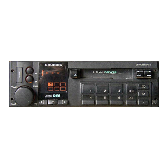
WKC 2670 VD
~WKC 3670 ~
~ WKG 2670 VD (Sach -Nr. / Order No. 9.18202 - 8151)
WKC 3670 (Sach.-Nr. / Order No. 9.18203 - 8151)
Contents
Mechanical Section
General
_
Disassembly Instructions
Take - up torque of the clutches, Head Height —
Azimuth
Electrical Section
Legend
Alignment Table
Alignment Layout
List of Spare Parts
List of Spare Parts Tape Drive S 281 V
List of Spare Parts WKC 2670 VD
List of Spare Parts WKC 3670
WKC - Scanning
Notes on components
Printed Circuit Boards / Connecting Diagrams
PCB WKC 2670 VD/3670
|
PCB WKC 2670 VD
Connection Diagram WKC 2670 VD
PCB WKC 3670
Connection Diagram
WKC 3670
N.B. When carrying out repairs, observe MOS precautions!
Page
10-12
13-18
19-24
25-28
29
30
31-34
35-46
47-50
51-62
— Subject to alteration
Printed in Germany
VK 226 0791
ervice
Manual!
Order
Servicemanual Sach-Nr.
0.
72010-719.10
5
2yMe
Werbung


