
Inhaltszusammenfassung für Stahl Ex nR Control Panel 9851/5 Serie
- Seite 1 Betriebsanleitung Additional languages r-stahl.com Ex nR Control Panel Reihe 9851/5...
-
Seite 2: Inhaltsverzeichnis
Inhaltsverzeichnis Inhaltsverzeichnis Allgemeine Angaben....................3 Hersteller......................3 Zu dieser Betriebsanleitung .................3 Weitere Dokumente .....................3 Konformität zu Normen und Bestimmungen ............3 Erläuterung der Symbole ..................4 Symbole in der Betriebsanleitung ................4 Symbole am Gerät ....................4 Sicherheit ......................5 Bestimmungsgemäße Verwendung..............5 Qualifikation des Personals .................5 Restrisiken ......................6 Transport und Lagerung ..................7 Produktauswahl und Projektierung ..............8 Montage und Installation..................9... -
Seite 3: Allgemeine Angaben
▶ Betriebsanleitung dem Bedien- und Wartungspersonal jederzeit zugänglich machen. ▶ Betriebsanleitung an jeden folgenden Besitzer oder Benutzer des Geräts weitergeben. ▶ Betriebsanleitung bei jeder von R. STAHL erhaltenen Ergänzung aktualisieren. ID-Nr.: 284189 / 985160310020 Publikationsnummer: 2021-07-20·BA00·III·de·02 Die Originalbetriebsanleitung ist die deutsche Ausgabe. -
Seite 4: Erläuterung Der Symbole
Erläuterung der Symbole Erläuterung der Symbole Symbole in der Betriebsanleitung Symbol Bedeutung Hinweis zum leichteren Arbeiten Gefahrensituation, die bei Nichtbeachtung der GEFAHR! Sicherheitsmaßnahmen zum Tod oder zu schweren Verletzungen mit bleibenden Schäden führen kann. Gefahrensituation, die bei Nichtbeachtung der WARNUNG! Sicherheitsmaßnahmen zu schweren Verletzungen führen kann. -
Seite 5: Sicherheit
Normen und Bestimmungen umfasst. Für Tätigkeiten in explosionsgefährdeten Bereichen sind weitere Kenntnisse erforderlich! R. STAHL empfiehlt einen Kenntnisstand, der in folgenden Normen beschrieben wird: • IEC/EN 60079-14 (Projektierung, Auswahl und Errichtung elektrischer Anlagen) • IEC/EN 60079-17 (Prüfung und Instandhaltung elektrischer Anlagen) •... -
Seite 6: Restrisiken
Gewicht des Geräts beachten. ▶ Gerät nicht belasten. ▶ Verpackung und Gerät auf Beschädigung prüfen. Beschädigungen umgehend an R. STAHL melden. Beschädigtes Gerät nicht in Betrieb nehmen. ▶ Gerät in Originalverpackung, trocken (keine Betauung), in stabiler Lage und sicher vor Erschütterungen lagern. ▶... -
Seite 7: Verletzungsgefahr
Transport und Lagerung Unsachgemäße Montage, Installation, Inbetriebnahme, Instandhaltung oder Reinigung Grundlegende Arbeiten wie Montage, Installation, Inbetriebnahme, Instandhaltung oder Reinigung des Geräts dürfen nur nach gültigen nationalen Bestimmungen des Einsatzlandes und von qualifizierten Personen durchgeführt werden. Ansonsten kann der Explosionsschutz aufgehoben werden. Explosionen mit tödlichen oder schweren Verletzungen von Personen können die Folge sein. -
Seite 8: Produktauswahl Und Projektierung
Produktauswahl und Projektierung Austausch oder Nachrüstung von weiteren Einbauten im Ex nR oder Ex ec Gehäuseteil Die Ex nR Steuerung wird von R. STAHL projektiert und komplett einsatzbereit inklusive der Einbauten wie z.B. WLAN Access Points ausgeliefert. Das Erwärmungsverhalten wird durch R. -
Seite 9: Montage Und Installation
Montage und Installation Montage und Installation Montage / Demontage ▶ Gerät sorgfältig und nur unter Beachtung der Sicherheitshinweise (siehe Kapitel "Sicherheit") montieren. ▶ Folgende Einbaubedingungen und Montageanweisungen genau durchlesen und exakt befolgen. 6.1.1 Gebrauchslage GEFAHR! Explosion durch falsche Montagelage! Nichtbeachten führt zu tödlichen oder schweren Verletzungen. ▶... -
Seite 10: Installation
GEFAHR! Explosion durch nachträgliche, komplette Lackierung des Geräts! Nichtbeachten führt zu tödlichen oder schweren Verletzungen. ▶ Gerät nicht lackieren. ▶ Vor der Ausbesserung z.B. von Kratzern Rücksprache mit R. STAHL halten. Ex nR Control Panel 284189 / 985160310020 Reihe 9851/5 2021-07-20·BA00·III·de·02... - Seite 11 Montage und Installation GEFAHR! Explosion durch fehlende Abdichtung! Nichtbeachten führt zu tödlichen oder schweren Verletzungen. ▶ Verschlussstopfen an der freien Kabelverschraubung zwischen Anschlussraum und Ex nR Gehäuse anbringen (Anzugsdrehmoment 4 Nm). 22849E00 Die notwendigen technischen Details/Daten zur elektrischen Installation befinden sich in folgenden Unterlagen: ▶...
-
Seite 12: Gehäuse Öffnen Und Schließen
▶ Vor dem Schließen des Geräts sorgfältig die Dichtungen des Deckels und des Geräts prüfen. Ausrichtung des Deckels beachten. ▶ Bei Beschädigungen Gerät nicht in Betrieb setzen, R. STAHL kontaktieren. Ex nR Control Panel 284189 / 985160310020 Reihe 9851/5 2021-07-20·BA00·III·de·02... - Seite 13 Montage und Installation Öffnen und Schließen des Ex ec Gehäuseteils / Anschlussraum Das Ex ec Gehäuseteil ist zum Anschluss der Stromversorgung bzw. der drahtgebundenen Signalübertragung vorgesehen. ▶ 4 Schrauben mit einem geeigneten Schraubendreher lösen. ▶ Vorsichtig den Deckel öffnen. ▶ Darauf achten, dass der Deckel nicht beschädigt wird.
-
Seite 14: Anschluss Ethernet Über Patch-Panel Mit Federzugklemmen
Montage und Installation 6.2.2 Anschluss Ethernet über Patch-Panel mit Federzugklemmen 1 2 3 6 Ø 4 5 7 8 22850E00 Legende = Steckbrücke zur Auswahl = RJ45-Buchse (TP-Port) der Schirmerdung = Federanschlussklemmen = Universalrastfuß für für Feldverkabelung EN-Tragschienen = EN-Tragschiene = Zugentlastung mit Schirmanschluss 22851E00... -
Seite 15: Anschluss Ethernet Über Patch-Panel Mit Schraubklemmen
Montage und Installation 6.2.3 Anschluss Ethernet über Patch-Panel mit Schraubklemmen Ø 22852E00 Legende = Steckbrücke zur Auswahl = RJ45-Buchse (TP-Port) der Schirmerdung = Schraubanschlussklemmen = Universalrastfuß für für Feldverkabelung EN-Tragschienen = EN-Tragschiene = Zugentlastung mit Schirmanschluss 22851E00 a = 10 mm b = 35 mm c = 5 mm ▶... -
Seite 16: Anschluss Ethernet Mit Ethernetklemme 8187
Montage und Installation 6.2.4 Anschluss Ethernet mit Ethernetklemme 8187 21948E00 Legende = Platinenträger = Schirmklemmen = Schnappriegel = 2-polige Klemmblöcke 15477E00 a = 5 ..7 mm b = < 10 mm c = 35 ... 45 mm d = 20 ... 25 mm ▶... -
Seite 17: Inbetriebnahme
Inbetriebnahme 6.2.5 Anschlussbelegung und Farbcodierung Eingangs- Ausgangs- Funktion Aderpaar Aderpaar typische typische klemme klemme nach nach Farbe nach Farbe nach TIA 568A TIA 568B TIA 568A TIA 568B weiß / grün weiß / orange grün / weiß orange / weiß oder grün oder orange –... -
Seite 18: Instandhaltung, Wartung, Reparatur
Bei beschädigter Dichtung: • Gerät unverzüglich außer Betrieb setzen. • Deckel gegen ein Originalteil von R. STAHL austauschen. Bei dem Ex nR Control Panel 9851/5 handelt es sich um ein Ex nR Gehäuse ohne Prüfanschluss gemäß IEC/EN 60079-15. Daher ist keine regelmäßige Überprüfung der Dichtigkeit mit einem Druckmessgerät erforderlich. -
Seite 19: Rücksendung
▶ Rücksendung bzw. Verpackung der Geräte nur in Absprache mit R. STAHL durchführen! Dazu mit der zuständigen Vertretung von R. STAHL Kontakt aufnehmen. Für die Rücksendung im Reparatur- bzw. Servicefall steht der Kundenservice von R. STAHL zur Verfügung. ▶ Kundenservice persönlich kontaktieren. -
Seite 20: 13.1 Technische Daten
(keine Betauung) Verwendung in Höhe < 2000 m Mechanische Daten Schutzart IP 66 (Gehäuse mit Kabelverschraubungen Reihe 8161) Material Gehäuse Polyesterharz, glasfaserverstärkt Dichtung Silikon, geschäumt Weitere technische Daten, siehe r-stahl.com. Ex nR Control Panel 284189 / 985160310020 Reihe 9851/5 2021-07-20·BA00·III·de·02... -
Seite 21: 14.1 Geräteaufbau
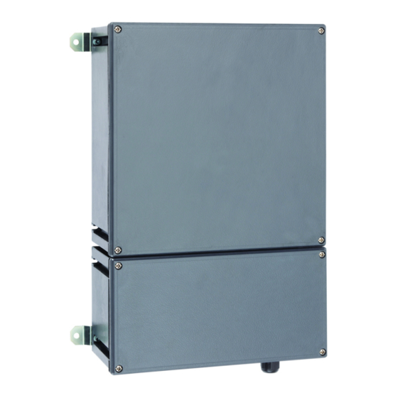
Anhang B Anhang B 14.1 Geräteaufbau Geräteelement Beschreibung Ex nR Gehäuseteil Bietet den Explosionsschutz für das eingebaute Gerät für die Installation in Zone 2. Öffnen nur im Fall des Austauschs um mögliche Undichtigkeiten zu vermeiden. Ex ec Gehäuseteil Erlaubt den Anschluss von (Anschlussraum) Ethernet-Leitungen für die Kommunikation und... - Seite 22 Anhang B Maßzeichnungen (alle Maße in mm [Zoll]) – Änderungen vorbehalten 340,50 [13,41] 380 [14,96] 22216E00 9851/51-73-73 Ex nR Control Panel 284189 / 985160310020 Reihe 9851/5 2021-07-20·BA00·III·de·02...
- Seite 23 Operating instructions Additional languages r-stahl.com Ex nR Control Panel Series 9851/5...
- Seite 24 Contents Contents General Information .....................3 Manufacturer......................3 About these Operating Instructions..............3 Further Documents ....................3 Conformity with Standards and Regulations............3 Explanation of Symbols ..................4 Symbols used in these Operating Instructions.............4 Symbols on the Device ..................4 Safety........................5 Intended Use......................5 Personnel Qualification ..................5 Residual Risks .....................6 Transport and Storage ..................7 Product Selection and Project Engineering ............8 Mounting and Installation ..................9...
-
Seite 25: General Information
Make the operating instructions accessible to operating and maintenance staff at all times. ▶ Pass the operating instructions on to each subsequent owner or user of the device. ▶ Update the operating instructions every time R. STAHL issues an amendment. ID no.: 284189 / 985160310020 Publication code: 2021-07-20·BA00·III·en·02... -
Seite 26: Explanation Of Symbols
Explanation of Symbols Explanation of Symbols Symbols used in these Operating Instructions Symbol Meaning Handy hint for making work easier Dangerous situation which can result in fatal or severe injuries DANGER! causing permanent damage if the safety measures are not complied with. -
Seite 27: Safety
Specialists who perform these activities must have a level of knowledge that meets applicable national standards and regulations. Additional knowledge is required for any activity in hazardous areas! R. STAHL recommends having a level of knowledge equal to that described in the following standards: •... -
Seite 28: Residual Risks
▶ Do not place any loads on the device. ▶ Check the packaging and the device for damage. Report any damage to R. STAHL immediately. Do not commission a damaged device. ▶ Store the device in its original packaging in a dry place (with no condensation), and make sure that it is stable and protected against the effects of vibrations and knocks. -
Seite 29: Risk Of Injury
Transport and Storage Improper mounting, installation, commissioning, maintenance or cleaning Basic work such as mounting, installation, commissioning, maintenance or cleaning of the device must be performed only in accordance with the applicable national regulations of the country of use and only by qualified persons. Otherwise, the explosion protection may be rendered ineffective. -
Seite 30: Product Selection And Project Engineering
Replacement or retrofit of further built-in components in the Ex nR or Ex ec enclosure part The Ex nR control system has been planned by R. STAHL and is supplied fully ready for use, including the built-in components such as the WiFi Access Points. The heat dissipation has been checked by R. -
Seite 31: Mounting And Installation
Mounting and Installation Mounting and Installation Mounting/Dismounting ▶ Mount the device carefully and only in accordance with the safety information (see "Safety" chapter). ▶ Read through the following installation conditions and assembly instructions carefully and follow them precisely. 6.1.1 Operating Position DANGER! Risk of explosion if device installed in incorrect mounting position! Non-compliance results in fatal or severe injuries. -
Seite 32: Installation
▶ Before use in areas with continuously high humidity and high temperature variations, such as the conditions in tropical and sub-tropical climate zones, contact R. STAHL. ▶ Do not create any cold bridges (condensation hazard). If necessary, install the enclosure with a clearance to minimise condensation in the enclosure. - Seite 33 Mounting and Installation DANGER! Explosion caused by insufficient seal! Non-compliance results in fatal or severe injuries. ▶ Attach the stopping plug on the free cable gland between the connection chamber and the Ex nR enclosure (tightening torque 4 Nm). 22849E00 The necessary technical details/data on electrical installation can be found in the following documents: ▶...
- Seite 34 Before closing the device, carefully check the seals on the cover and the device. Note the alignment of the cover. ▶ If any damage is discovered, do not commission the device and contact R. STAHL. Ex nR Control Panel 284189 / 985160310020 Series 9851/5 2021-07-20·BA00·III·en·02...
- Seite 35 Mounting and Installation Opening and closing the Ex ec enclosure part/connection chamber The Ex ec enclosure part is intended for connecting the power supply and/or wired signal transmission. ▶ Undo the 4 screws using a suitable screwdriver. ▶ Carefully open the cover. ▶...
- Seite 36 Mounting and Installation 6.2.2 Ethernet Connection via Patch Panel with Spring Clamp Terminals 1 2 3 6 Ø 4 5 7 8 22850E00 Legend = Plug-in jumper for shielding = RJ45 socket (TP port) earthing selection = Spring connection terminals = Universal snap foot for for field wiring EN mounting rails...
- Seite 37 Mounting and Installation 6.2.3 Ethernet Connection via Patch Panel with Screw Terminals Ø 22852E00 Legend = Plug-in jumper for shielding = RJ45 socket (TP port) earthing selection = Screw connection terminals = Universal snap foot for for field wiring EN mounting rails = EN mounting rails = Strain relief with shielding connection...
- Seite 38 Mounting and Installation 6.2.4 Ethernet Connection with Ethernet Terminal 8187 21948E00 Legend = PCB mount = Shielding terminals = Snap catch = 2-pole terminal blocks 15477E00 a = 5 to 7 mm b = < 10 mm c = 35 to 45 mm d = 20 to 25 mm ▶...
-
Seite 39: Commissioning
Commissioning 6.2.5 Terminal Assignment and Colour Coding Input Output Function Core pair Core pair Typical Typical terminal terminal as per as per colour as per colour as per TIA 568A TIA 568B TIA 568A TIA 568B White/green White/orange Green/white Orange/white or green or orange –... -
Seite 40: Maintenance, Overhaul, Repair
Perform overhaul of the device according to the applicable national regulations and the safety notes in these operating instructions ("Safety" chapter). Repairs ▶ Repair work on the device must be performed only by R. STAHL. ▶ Built-in components must only be replaced with identical devices. Ex nR Control Panel... -
Seite 41: Returning The Device
Returning the Device ▶ Only return or package the devices after consulting R. STAHL! Contact the responsible representative from R. STAHL. R. STAHL's customer service is available to handle returns if repair or service is required. ▶ Contact customer service personally ▶... -
Seite 42: Appendix A
< 2000 m Mechanical data Degree of protection IP 66 (enclosure with series 8161 cable glands) Material Enclosure Polyester resin, glass fibre reinforced Seal Silicone, foamed For further technical data, see r-stahl.com. Ex nR Control Panel 284189 / 985160310020 Series 9851/5 2021-07-20·BA00·III·en·02... -
Seite 43: Appendix B
Appendix B Appendix B 14.1 Device Design Device element Description Ex nR enclosure part Provides explosion protection for the installed device for installation in Zone 2. Only open in the event of replacement, in order to prevent potential leaks. Ex ec enclosure part Enables the connection of (connection Ethernet conductors for... - Seite 44 Appendix B Dimensional drawings (all dimensions in mm [inches]) – Subject to change 340,50 [13,41] 380 [14,96] 22216E00 9851/51-73-73 Ex nR Control Panel 284189 / 985160310020 Series 9851/5 2021-07-20·BA00·III·en·02...