Herunterladen Inhalt Inhalt Diese Seite drucken
Inhaltsverzeichnis

Werbung

Verfügbare Sprachen
  • DE

Verfügbare Sprachen

  • DEUTSCH, seite 1
VICTORIA 60
Dunstabzugshaube
Range Hood
Campana extractora
Hotte aspirante
Cappa aspirante
10036447 10036448 10036449
10036450 10036451
www.klarstein.com

Werbung

Inhaltsverzeichnis
loading

Inhaltszusammenfassung für Klarstein VICTORIA 60

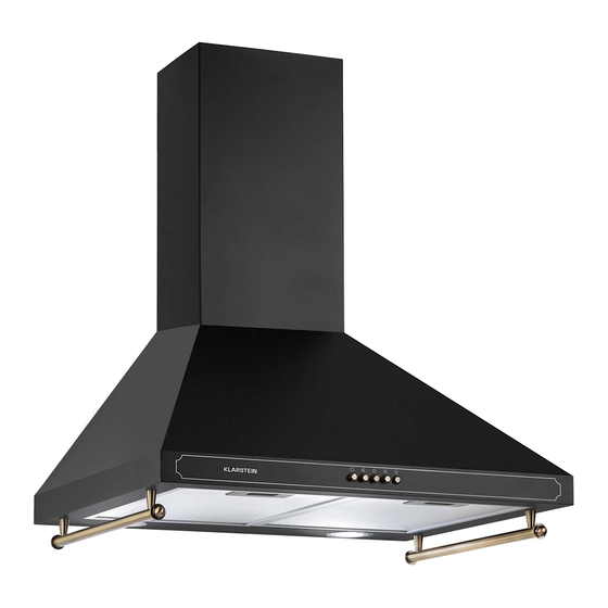
  • Seite 1 VICTORIA 60 Dunstabzugshaube Range Hood Campana extractora Hotte aspirante Cappa aspirante 10036447 10036448 10036449 10036450 10036451 www.klarstein.com...
  • Seite 3: Inhaltsverzeichnis

    Sehr geehrter Kunde, wir gratulieren Ihnen zum Erwerb Ihres Gerätes. Lesen Sie die folgenden Hinweise sorgfältig durch und befolgen Sie diese, um möglichen Schäden vorzubeugen. Für Schäden, die durch Missachtung der Hinweise und unsachgemäßen Gebrauch entstehen, übernehmen wir keine Haftung. Scannen Sie den folgenden QR-Code, um Zugriff auf die aktuellste Bedienungsanleitung und weitere Informationen rund um das Produkt zu erhalten.
  • Seite 4: Sicherheitshinweise

    SICHERHEITSHINWEISE • Lesen Sie sich alle Hinweise vor der Benutzung sorgfältig durch und bewahren Sie die Bedienungsanleitung zum späteren Nachschlagen gut auf. • Die Montagearbeiten dürfen nur von einer Elektrofachkraft oder einer qualifizierten Person durchgeführt werden. Bevor Sie die Dunstabzugshaube verwenden, stellen Sie sicher, dass die Spannung (V) und die auf der Dunstabzugshaube angegebene Frequenz (Hz) der Spannung und Frequenz der Stromversorgung in Ihrem Haushalt entsprechen.
  • Seite 5 Wichtige Hinweise zum Abluftbetrieb WARNUNG Vergiftungsgefahr durch zurückgesaugte Abgase! Betreiben Sie das Gerät nicht im Abluftbetrieb, wenn es zusammen mit einer raumluftabhängigen Feuerstätte betrieben wird und keine ausreichende Luftzirkulation garantiert wird. Raumluftabhängige Feuerstätten wie Gas-, Öl-, Holz- oder Kohleheizungen, Boiler oder Durchlauferhitzer beziehen die Luft aus dem Raum und führen sie durch ein Abluftrohr oder einen Kamin ins Freie.
  • Seite 6: Geräteübersicht

    GERÄTEÜBERSICHT Stk. Gerätekomponenten Gerätekorpus, inklusive: Bedienelementen, Licht, Gebläse, Filter Untere Abdeckung Obere Abdeckung Bund (optional) Abluftrohr Aktivkohlefilter (optional) Hinweis: Das optionale Zubehör ist nicht im Lieferumfang enthalten.
  • Seite 7: Installationszubehör

    INSTALLATIONSZUBEHÖR Standard-Installationszubehör Stk. Teil Schrauben 5 x 50 Dübel Schrauben 4,2 x 9,5 Schrauben 5 x 12 Befestigungswinkel Abzugshaube Befestigungswinkel Abdeckung (optional) Optionales Installationszubehör (nicht im Lieferumfang enthalten) Stk. Teil Schrauben 5 x 50 Dübel Schrauben 4,2 x 9,5 Befestigungswinkel Abzugshaube Befestigungswinkel Abdeckung (optional) Hinweis: Falls Sie die Installationskomponenten aus diese Tabelle auswählen, richten Sie sich nach der Angabe „Lösung 2“...
  • Seite 8: Abmessungen Und Abstände

    ABMESSUNGEN UND ABSTÄNDE Hinweis: Bei den angegebenen Werten handelt es sich um [mm].
  • Seite 9 Maße Option Abzug 400+0 400+300 628-910 400+390 628-1000 500+490 728-1200 Hinweis: Bei den angegebenen Werten handelt es sich um [mm].
  • Seite 10: Installation

    INSTALLATION Hinweis: Bei den angegebenen Werten handelt es sich um [mm]. Option Abzug 400+0 400+300 390-620 400+390 390-710 500+490 490-910 Referenzlinie Markierungslinien Ziehen Sie als ersten Schritt zunächst folgende Linien: • Eine senkrechte Referenzlinie zur Decke oder zu der oberen Begrenzung, im Zentrum der Stelle, an der die Dunstabzugshaube angebracht werden soll.
  • Seite 11 Markierungspunkte Hinweis: Bei den angegebenen Werten handelt es sich um [mm]. (1) Markieren Sie einen Punkt (1) auf der horizontalen Linie A, 80 mm rechts von der vertikalen Referenzlinie. Wiederholen Sie diesen Schritt auf der linken Seite der Referenzlinie und auf der Referenzlinie selbst. Am Ende sollten Sie 3 Punkte haben, die sich auf derselben Höhe befinden.
  • Seite 12: Anbringen Des Dunstabzugs

    Verbindung mit dem Abluftsystem Verbinden Sie die Dunstabzugshaube bei der Installation mit dem Dunstabzug. Verwenden Sie hierfür entweder ein flexibles oder ein starres Rohr mit einem Durchmesser von 150 mm oder 120 mm. Welches Rohr Sie wählen bleibt Ihnen überlassen. •...
  • Seite 13: Bedienfeld Und Tastenfunktionen

    Obere Abdeckung • Fixieren Sie die obere Abdeckung mit 2 Schrauben (4,2x9,5) an dem Befestigungswinkel. BEDIENFELD UND TASTENFUNKTIONEN Bedienfeld Tastenfunktionen Ein-/Aus: Drücken Sie zum Ein- und Ausschalten diese Taste. Geschwindigkeitsregler: Wenn Sie diese Taste drücken, läuft das Gerät mit langsamer Geschwindigkeit. Geschwindigkeitsregler: Wenn Sie diese Taste drücken, läuft das Gerät mit mittlerer Geschwindigkeit.
  • Seite 14: Reinigung Und Pflege

    REINIGUNG UND PFLEGE Reinigung der Fettfiltern • Die Filter müssen, abhängig von der Verwendungshäufigkeit, mindestens alle 2 Monate gereinigt werden. Die Filter sind spülmaschinengeeignet. • Entnehmen Sie die Filter, indem Sie diese gegen die Rückseite der Dunstabzugshaube drücken und gleichzeitig nach unten ziehen. •...
  • Seite 15 Austausch der Aktivkohlefilter: Entnehmen Sie den metallenen Fettfilter. Entnehmen Sie die verschmutzten Aktivkohlefilter. Setzen Sie die neuen Aktivkohlefilter ein. Setzen Sie den metallenen Fettfilter wieder ein. Befestigen: Entfernen: 1. Einsetzen 2. Nach vorne 1. Nach vorne drückern ziehen 2. Abnehmen Entfernen: Befestigen: 1.
  • Seite 16: Fehlersuche Und Fehlerbehebung

    Ersatzlicht ILCOS D Ø Leistung Spannung Bild code DSR- 70 mm 1,5 W DC 12 V 1.5-S-70 Wiedereinsetzen des LED-Lichtmoduls Drücken Sie das LED-Licht in die Front der vorderen Abdeckung und fixieren Sie dieses dort. Verbinden Sie die Klemme mit dem LED-Licht. Drehen Sie vorsichtig die beiden Schrauben der vorderen Abdeckung wieder fest.
  • Seite 17 Problem Ursache Lösung Vibration Die Flügelblätter können, Ersetzen Sie die wenn Sie blockiert sind, Flügelblätter. Vibrationen verursachen. Der Motor ist nicht richtig Befestigen Sie den Motor befestigt. richtig. Die Dunstabzugshaube ist Befestigen Sie die nicht richtig befestigt. Dunstabzugshaube richtig. Unzureichende Die Entfernung zwischen Passen Sie den Abstand Luftabsaugung...
  • Seite 18: Produktdatenblatt

    PRODUKTDATENBLATT Angaben nach Verordnung (EU) Nr. 65/2014 Mess- und Berechnungsmethoden nach EN 61591:1997+A1:2006+A2:201 1+A1 1:201 4+A12:2015 Artikelnummer 10036447, 10036448, 10036449, 10036450, 10036451 Bezeichnung Symbol Wert Einheit Jährlicher Energieverbrauch 90,6 kWh/Jahr hood Energieeffizienzklasse fluiddynamische Effizienz 19,6 hood Klasse für die fluiddynamische Effizienz Beleuchtungseffizienz Lux/W...
  • Seite 19 Angaben nach Verordnung (EU) Nr. 66/2014 Mess- und Berechnungsmethoden nach EN 61591:1997+A1:2006+A2:201 1+A1 1:201 4+A12:2015 Artikelnummer 10036447, 10036448, 10036449, 10036450, 10036451 Bezeichnung Symbol Wert Einheit Jährlicher Energieverbrauch 90,6 kWh/Jahr hood Zeitverlängerungsfaktor Fluiddynamische Effizienz 19,6 hood Energieeffizienzindex 75,8 hood Gemessener Luftvolumenstrom im m³/h Bestpunkt Gemessener Luftdruck im Bestpunkt...
  • Seite 20: Hinweise Zum Umweltschutz

    HINWEISE ZUM UMWELTSCHUTZ • Achten Sie während des Kochens auf eine ausreichende Luftzufuhr, damit die Dunstabzugshaube effizient und mit einem geringen Betriebsgeräusch arbeiten kann. • Passen Sie die Gebläsedrehzahl an die beim Kochen entstehende Dampfmenge an. Verwenden Sie den Intensivmodus nur bei Bedarf. Je niedriger die Gebläsedrehzahl ist, desto weniger Energie wird verbraucht.
  • Seite 21 Dear Customer, Congratulations on purchasing this device. Please read the following instructions carefully and follow them to prevent possible damages. We assume no liability for damage caused by disregard of the instructions and improper use. Scan the QR code to get access to the latest user manual and more product information.
  • Seite 22: Safety Instructions

    SAFETY INSTRUCTIONS • Thank you for purchasing this cooker hood. Please read the instruction manual carefully before you use the cooker hood, and keep it in a safe place. • The installation work must be carried out by a qualified electrician or competent person.
  • Seite 23 Important notes about the extraction mode WARNING Risk of poisoning from exhaust gases sucked back. Never operate the device in extraction mode simultaneously with an open flue appliance when there is not adequate airflow guaranteed. Open fl ue combustion equipment (for example, gas, oil, wood or coal-fi red heaters, tankless water heaters, water heaters) pulls combustion air from the room and runs it through an exhaust pipe or chimney to the outside.
  • Seite 24: Product Description

    PRODUCT DESCRIPTION Ref. Qty. Product Components Hood Body, complete with: Controls, Light, Blower, Filter. Lower Decorative Chimney Upper Decorative Chimney Flange (optional) Exhaust Pipe The Activated Charcoal filter (optional) Note: The optional accessory is not included in the delivery.
  • Seite 25: Installation Components

    INSTALLATION COMPONENTS Standard Installation Components Ref. Qty. Component Screws 5 x 50 Wall Plugs Screws 4,2 x 9,5 Screws 5 x 12 Hood fixing bracket Chimney fixing bracket (optional) Optional Installation Components (not included in the delivery) Ref. Qty. Component Screws 5 x 50 Wall Plugs Screws 4,2 x 9,5...
  • Seite 26: Dimensions

    DIMENSIONS Note: The specified values are [mm].
  • Seite 27 Dimensions Option Chimney 400+0 400+300 628-910 400+390 628-1000 500+490 728-1200 Note: The specified values are [mm].
  • Seite 28: Installation

    INSTALLATION Note: The specified values are [mm]. Option Chimney 400+0 400+300 390-620 400+390 390-710 500+490 490-910 Vertical line Wall Drilling and Bracket Fixing As a first step, proceed with the following drawings: • A vertical line up to the ceiling or up to the upper limit, at the center of the area in which the hood is to be fitted.
  • Seite 29 Mark Points Note: The specified values are [mm]. (1) Mark a point (1) on the horizontal line A, 80 mm to the right of the vertical reference line. Repeat this operation on the other side and on the vertical reference line, checking that the three marks are leveled.
  • Seite 30: Chimney Assembly

    Connections to ducted version air exhaust system When installing the ducted version, connect the hood to the chimney using either a flexible or rigid pipe 150 mm or 120 mm, the choice of which is left to the installer. • If to install a 120 mm air exhaust connection, insert the reducer flange on the hood body outlet.
  • Seite 31: Control Panel And Key Functions

    Upper Decorative Chimney • Fix the upper chimney onto the bracket with 2 screws 12 (4.2x 9.5) supplied with the hood. CONTROL PANEL AND KEY FUNCTIONS Control Panel Key Functions Off motor switch: press on this switch to stop the motor operation. Speed switch: press on this switch, the motor runs at low speed.
  • Seite 32: Care And Cleaning

    CARE AND CLEANING Grease Filters • The filters must be cleaned every 2 months of operation, or more frequently for particularly heavy usage, and can be washed in a dishwasher. • Remove the filters one by one pushing them towards the back side of the hood unit and simultaneously pulling downwards.
  • Seite 33 Replacing the activated charcoal filter: Remove the metal grease filters Remove the saturated activated charcoal filter. Fit the new filters. Replace the metal grease filters. Fix: Remove: 1. Put in 1. Pull forward 2. Push forward 2. Remove Remove: Fix: 1.
  • Seite 34: Troubleshooting

    Replacement Light ILCOS D Ø Max Power Voltage Picture code DSR- 70 mm 1,5 W DC 12 V 1.5-S-70 Reinstall LED Light Module Press LED light on the front of front plate, install the LED light on the front plate. Connect the terminal of LED light and light leads.
  • Seite 35 Problem Cause Solution Vibration The blade, if damaged, Replace the blade. can cause vibrating. The motor is not tightly Fasten the motor tightly. fastened. The cooker hood is not Fixed the cooker hood tightly fixed. tightly. Insufficient suction The distance between Readjust the distance.
  • Seite 36: Product Data Sheet

    PRODUCT DATA SHEET Information according to Regulation (EU) No. 65/2014 Measurement and calculation methods according to EN 61591:1997+A1:2006+A2:20 1 1+A1 1:2014+A12:2015 Item number Description Symbol Value Unit Annual Energy Consumption 90,6 kWh/Jahr hood Energy Efficiency class Fluid Dynamic Efficiency 19,6 hood Fluid Dynamic Efficiency class Lighting Efficiency...
  • Seite 37 Information according to Regulation (EU) No. 66/2014 Measurement and calculation methods according to EN 61591:1997+A1:2006+A2:20 1 1+A1 1:2014+A12:2015 Item number Description Symbol Value Unit Annual Energy Consumption 90,6 kWh/Jahr hood Time increase factor Fluid Dynamic Efficiency 19,6 hood Energy Efficiency Index 75,8 hood Measured air flow rate at best...
  • Seite 38: Notes On Environmental Protection

    NOTES ON ENVIRONMENTAL PROTECTION • During cooking, make sure that there is sufficient air supply so that the cooker hood can operate efficiently and with low operating noise. • Adjust the fan speed to the amount of steam produced during cooking. Use the intensive mode only when necessary.
  • Seite 39: Datos Técnicos

    Estimado cliente, Le felicitamos por la adquisición de este producto. Lea atentamente las siguientes instrucciones y sígalas para evitar posibles daños. No asumimos ninguna responsabilidad por los daños causados por el incumplimiento de las instrucciones y el uso inadecuado. Escanee el siguiente código QR para obtener acceso a la última guía del usuario y más información sobre el producto.
  • Seite 40: Indicaciones De Seguridad

    INDICACIONES DE SEGURIDAD • Lea atentamente todas las indicaciones y conserve este manual para consultas posteriores. • Los trabajos de montaje deben ser realizados solamente por un electricista u otro profesional. Antes de utilizar la campana extractora, asegúrese de que la tensión (V) y la frecuencia indicada en la campana extractora (Hz) coinciden con la tensión (V) y frecuencia (Hz) de su suministro eléctrico.
  • Seite 41 Notas importantes acerca del modo de extracción ADVERTENCIA Peligro de muerte, riesgo de intoxicación provocado por gases en combustión aspirados. Nunca ponga en funcionamiento la función de extracción simultáneamente con un dispositivo que genere calor en una estancia estanca si no se ha garantizado una ventilación sufi ciente.
  • Seite 42: Descripción Del Aparato

    DESCRIPCIÓN DEL APARATO Núm. Uds. Componentes del aparato Base del aparato, que incluye: Elementos de control, luz, ventilador, filtro Cubierta inferior Cubierta superior Unión (opcional) Conducto de extracción Filtro de carbón activo (opcional) Advertencia: Los accesorios opcionales no están incluidos en el envío.
  • Seite 43: Accesorios De Instalación

    ACCESORIOS DE INSTALACIÓN Accesorios estándar para la instalación Núm. Uds. Pieza Tornillos 5 x 50 Tacos Tornillos 4,2 x 9,5 Tornillos 5 x 12 Soporte de fijación de la campana Soporte de fijación de la cubierta (opcional) Accesorios de instalación opcionales (No incluidos en el envío) Núm.
  • Seite 44: Dimensiones Y Distancias

    DIMENSIONES Y DISTANCIAS Advertencia: Las medidas indicadas se expresan en „mm“.
  • Seite 45 Dimensiones Opción Tiro 400+0 400+300 628-910 400+390 628-1000 500+490 728-1200 Advertencia: Las medidas indicadas se expresan en „mm“.
  • Seite 46: Instalación

    INSTALACIÓN Advertencia: Las medidas indicadas se expresan en „mm“. Opción Tiro 400+0 400+300 390-620 400+390 390-710 500+490 490-910 Línea de referencia Líneas de marca Como primer paso, marque las siguientes líneas: • Una línea de referencia vertical al techo o al límite superior en el centro del punto donde va a instalar la campana.
  • Seite 47 Puntos de marca Advertencia: Las medidas indicadas se expresan en „mm“. (1) Marque un punto (1) sobre la línea horizontal A, a 80 mm a la derecha de la línea de referencia vertical. Repita este paso en la parte izquierda de la línea de referencia y sobre la propia línea.
  • Seite 48: Montaje Del Tiro De Extracción

    Conexión con el sistema de extracción Una la campana con el tiro de extracción en la instalación. Utilice para ello un tubo flexible o rígido con un diámetro de 150 mm o 120 mm. Usted decide el tipo de tubo que emplea.
  • Seite 49: Panel De Control Y Funciones De Los Botones

    Cubierta superior • Fije la cubierta superior con 2 tornillos (4,2x9,5) al soporte de fijación. PANEL DE CONTROL Y FUNCIONES DE LOS BOTONES Panel de control Funciones de las teclas On/off: Encender y apagar el aparato con este botón. Regulador de velocidad: Si pulsa este botón, el aparato funcionará a velocidad baja.
  • Seite 50: Limpieza Y Cuidado

    LIMPIEZA Y CUIDADO Limpieza del filtro antigrasa • Los filtros deben limpiarse cada dos meses, independientemente de la frecuencia de uso. Los filtros pueden lavarse en el lavavajillas. • Retire los filtros presionándolos contra la parte trasera de la campana y tirando de ellos hacia abajo.
  • Seite 51 Sustitución del filtro de carbón activo: Retire el filtro antigrasa metálico. Retire el filtro de carbón activo sucio. Coloque el filtro nuevo de carbón activo. vuelva a colocar el filtro metálico antigrasa. Fijar: 1. Colocar Retirar: 2. Presionar hacia 3. Tirar hacia adelante adelante 4.
  • Seite 52: Detección Y Resolución De Problemas

    Luz de repuesto ILCOS D Ø Potencia Potencia Imagen code DSR- 70 mm 1,5 W DC 12 V 1.5-S-70 Colocación del módulo de luz LED Presione la luz LED en la parte frontal de la cubierta delantera y fíjela. Una la abrazadera a la luz LED. Atornille con cuidado ambos tornillos de la cubierta delantera.
  • Seite 53 Problema Causa Solución Vibraciones Las aspas del ventilador Sustituya las aspas del pueden provocar ventilador. vibraciones cuando están bloqueadas. El motor no se ha colgado Fije el motor correctamente. correctamente. La campana no se ha Fije la campana colgado correctamente. correctamente.
  • Seite 54: Ficha Técnica Del Producto

    FICHA TÉCNICA DEL PRODUCTO Información según el Reglamento (UE) nº 65/2014 Métodos de medición y cálculo según EN 61591:1997+A1:2006+A2:201 1+A1 1:2014 +A12:2015 Número de artículo Descripción Símbolo Valor Unidad Consumo anual de energía 90,6 kWh/Jahr hood Clase de eficiencia energética eficiencia fluidodinámica 19,6 hood...
  • Seite 55 Datos según el Reglamento (UE) nº 66/2014 Métodos de medición y cálculo según EN 61591:1997+A1:2006+A2:201 1+A1 1:2014 +A12:2015 Número de artículo Descripción Símbolo Valor Unidad Consumo anual de energía 90,6 kWh/Jahr hood Factor de extensión temporal eficiencia fluidodinámica 19,6 hood Índice de eficiencia energética 75,8 hood...
  • Seite 56: Notas Para Cuidar Del Medio Ambiente

    NOTAS PARA CUIDAR DEL MEDIO AMBIENTE • Durante la cocción, asegúrese de que haya un flujo de aire suficiente para que la campana extractora funcione eficazmente y con poco ruido de funcionamiento. • Ajuste la velocidad del ventilador a la cantidad de vapor producida durante la cocción.
  • Seite 57: Fiche Technique

    Chère cliente, cher client, Toutes nos félicitations pour l’acquisition de ce nouvel appareil. Veuillez lire attentivement et respecter les instructions de ce mode d’emploi afin d’éviter d’éventuels dommages. Nous ne saurions être tenus pour responsables des dommages dus au non-respect des consignes et à...
  • Seite 58: Consignes De Sécurité

    CONSIGNES DE SÉCURITÉ • Lisez attentivement toutes les consignes avant d’utiliser l’appareil et conservez ce mode d’emploi pour vous y référer ultérieurement. • Les travaux de montage doivent être effectués uniquement par électricien professionnel ou un spécialiste. Avant d‘utiliser la hotte aspirante, assurez-vous que la tension (V) et la fréquence indiquée sur la hotte aspirante (Hz) correspondent à...
  • Seite 59 Remarques importantes concernant le mode d‘extraction MISE EN GARDE Danger de mort, risques d‘intoxication ! Par la ré-aspiration de gaz de combustion. Ne jamais utiliser la fonction d’aspiration de l’appareil en même temps qu’un foyer dépendant de l’air ambiant si l’air frais est insuffi sant.
  • Seite 60: Aperçu De L'appareil

    APERÇU DE L‘APPAREIL N° Éléments de l'appareil Corps de l‘appareil, y compris : Éléments de commande, éclairage, ventilateur, filtre Habillage inférieur Habillage supérieur Collier (en option) Tube d'extraction Filtre à charbon actif (en option) Remarque : les accessoires en option ne sont pas fournis.
  • Seite 61: Accessoires D'installation

    ACCESSOIRES D‘INSTALLATION Accessoires d‘installation standard N° Pièce Vis 5 x 50 Chevilles Vis 4,2 x 9,5 Vis 5 x 12 Equerres de fixation de la hotte Equerres de fixation de l'habillage (en option) Accessoires optionnels d‘installation (non fournis) N° Pièce Vis 5 x 50 Chevilles Vis 4,2 x 9,5...
  • Seite 62: Dimensions Et Espacements

    DIMENSIONS ET ESPACEMENTS Remarque : les valeurs données ici sont exprimées en [mm].
  • Seite 63 Dimensions Option Extraction 400+0 400+300 628-910 400+390 628-1000 500+490 728-1200 Remarque : les valeurs données ici sont exprimées en [mm].
  • Seite 64: Installation

    INSTALLATION Remarque : les valeurs données ici sont exprimées en [mm]. Option Extraction 400+0 400+300 390-620 400+390 390-710 500+490 490-910 Ligne de référence Lignes repères Commencez par dessiner les lignes suivantes : • Une ligne de référence verticale au plafond ou à la limite supérieure, au centre de l‘emplacement où...
  • Seite 65 Points de repères Remarque : les valeurs données ici sont exprimées en [mm]. (1) Marquez un point (1) sur la ligne horizontale A, 80 mm à droite de la ligne de référence verticale. Répétez cette étape sur le côté gauche de la ligne de référence et sur la ligne de référence elle-même.
  • Seite 66: Montage De L'extraction D'air

    Branchement su système d‘extraction Connectez la hotte à au conduit d‘extraction pendant l‘installation. Utilisez un tube flexible ou rigide d‘un diamètre de 150 mm ou 120 mm. Le choix du tube vous appartient. • Si vous choisissez une connexion d‘évacuation de 120 mm de diamètre, ajoutez le collier à...
  • Seite 67: Panneau De Commande Et Fonctions Des Touches

    Habillage supérieur • Fixez l‘habillage inférieur avec 2 vis (4,2 x 9,5) sur l‘équerre de fixation. PANNEAU DE COMMANDE ET FONCTIONS DES TOUCHES Panneau de commande Fonctions des touches Marche/arrêt : appuyez sur cette touche pour allumer ou éteindre l'appareil. Réglage de la vitesse : lorsque vous appuyez sur cette touche, l'appareil fonctionne à...
  • Seite 68: Nettoyage Et Entretien

    NETTOYAGE ET ENTRETIEN Nettoyage des filtres à graisse • Les filtres doivent être nettoyés au moins tous les 2 mois suivant la fréquence d‘utilisation. Les filtres sont lavables au lave-vaisselle. • Retirez les filtres en les appuyant contre l‘arrière de la hotte et en les tirant vers le bas en même temps.
  • Seite 69 Remplacement des filtres à charbon actif : Retirez les filtres à graisse en métal. Retirez les filtres à charbon actif encrassés. Installez les nouveaux filtres à charbon actif. Remettez en place les filtres à graisse en métal Fixation : Démontage : 1.
  • Seite 70: Identification Et Résolution Des Problèmes

    Lampe de rechange ILCOS D Ø Puissance Tension Illustration code DSR- 70 mm 1,5 W DC 12 V 1.5-S-70 Réinstallation du module d‘éclairage LED Poussez la lumière LED en façade du capot avant et fixez-la. Branchez le connecteur à la lumière LED. Resserrez avec précaution les deux vis sur le couvercle avant.
  • Seite 71 Problème Cause Solution Vibration Les pales peuvent Remplacez les pales. provoquer des vibrations si elles sont bloquées. Le moteur n'est pas Fixez correctement le correctement fixé. moteur. La hotte n'est pas Fixez correctement la correctement fixée. hotte. Puissance d'extraction La distance entre la Ajustez la distance.
  • Seite 72: Fiche De Données Produit

    FICHE DE DONNÉES PRODUIT Informations selon le règlement (UE) n ° 65/2014 Méthodes de mesure et de calcul selon EN 61591:1997+A1:2006+A2:201 1+A1 1:201 4+A12:2015 Numéro d‘article Description Symbole Valeur Unité Consommation annuelle d'énergie 90,6 kWh/Jahr hood Classe d'efficacité énergétique Efficacité dynamique des fluides 19,6 hood Classe d'efficacité...
  • Seite 73 Informations selon le règlement (UE) n ° 66/2014 Méthodes de mesure et de calcul selon EN 61591:1997+A1:2006+A2:201 1+A1 1:201 4+A12:2015 Numéro d‘article Description Symbole Valeur Unité Consommation annuelle d'énergie 90,6 kWh/Jahr hood Facteur d'extension de temps Efficacité dynamique des fluides 19,6 hood Indice d'efficacité...
  • Seite 74: Informations Sur La Protection De L'environnement

    INFORMATIONS SUR LA PROTECTION DE L‘ENVIRONNEMENT • Assurez-vous qu‘il y a une ventilation suffisante pendant la cuisson pour que la hotte aspirante puisse fonctionner efficacement et avec un faible niveau sonore. • Ajustez la vitesse du ventilateur à la quantité de vapeur produite pendant la cuisson.
  • Seite 75 Gentile cliente, La ringraziamo per aver acquistato il dispositivo. La preghiamo di leggere attentamente le seguenti istruzioni per l’uso e di seguirle per evitare possibili danni. Non ci assumiamo alcuna responsabilità per danni scaturiti da una mancata osservazione delle avvertenze di sicurezza e da un uso improprio del dispositivo.
  • Seite 76: Avvertenze Di Sicurezza

    AVVERTENZE DI SICUREZZA • Leggere attentamente tutte le istruzioni prima dell´uso e conservare il manuale per consultazioni future. • Il montaggio può essere eseguito solo da un tecnico qualificato. Prima di utilizzare la cappa aspirante, accertarsi che la tensione (V) e la frequenza (Hz) indicate corrispondano alla tensione (V) e alla frequenza (Hz) domestiche.
  • Seite 77 Note importanti circa la modalità di estrazione AVVERTENZA Pericolo di morte, pericolo di intossicazione da gas di scarico! Non azionare l´apparecchio con funzione di scarico mentre è attivo un impianto di riscaldamento che utilizza l´aria ambiente, se l´areazione non è suffi ciente. Gli impianti di riscaldamento che sfruttano l´aria ambiente (ad es.
  • Seite 78: Descrizione Del Prodotto

    DESCRIZIONE DEL PRODOTTO Componenti Unità principale, inclusi: comandi, luce, ventola, filtro Camino decorativo inferiore Camino decorativo superiore Flangia (opzionale) Tubo di scarico Filtro a carboni attivi (opzionale) Nota: gli accessori opzionali non sono inclusi nella consegna.
  • Seite 79: Accessori Per L`installazione

    ACCESSORI PER L`INSTALLAZIONE Accessori per l´installazione standard Componente Viti 5 x 50 Tasselli Viti 4,2 x 9,5 Viti 5 x 12 Staffa di fissaggio cappa aspirante Staffa di fissaggio camino (opzionale) Accessori per l´installazione opzionali (non inclusi nella consegna) Componente Viti 5 x 50 Tasselli Viti 4,2 x 9,5...
  • Seite 80: Dimensioni E Distanze

    DIMENSIONI E DISTANZE Nota: i valori indicati sono in [mm].
  • Seite 81 Dimensioni Opzione Camino 400+0 400+300 628-910 400+390 628-1000 500+490 728-1200 Nota: i valori indicati sono in [mm].
  • Seite 82: Installation

    INSTALLATION Nota: i valori indicati sono in [mm]. Opzione Camino 400+0 400+300 390-620 400+390 390-710 500+490 490-910 Linea di riferimento Linee di marcatura Come primo passo, disegnare le seguenti linee: • Una linea di riferimento verticale al soffitto o alla delimitazione superiore, al centro del punto di installazione della cappa aspirante.
  • Seite 83 Punti di marcatura Nota: i valori indicati sono in [mm]. (1) Segnare un punto (1) sulla linea orizzontale A, 80 mm a destra della linea di riferimento verticale. Ripetere questo passaggio sul lato sinistro della linea di riferimento e sulla linea di riferimento stessa. Alla fine si otterranno 3 punti che si trovano alla stessa altezza.
  • Seite 84: Installare Il Camino

    Collegamento all‘impianto di scarico dell‘aria Collegare la cappa aspirante al camino. Utilizzare un tubo flessibile o rigido con un diametro di 150 mm o 120 mm. La scelta del tubo è dell´utente. • Se si sceglie una connessione per lo scarico da 120 mm, inserire la flangia all‘uscita dell’unità...
  • Seite 85: Pannello Dei Comandi E Tasti Funzione

    Camino decorativo superiore • Fissare il camino superiore alla staffa di montaggio utilizzando 2 viti (4.2x9.5). PANNELLO DEI COMANDI E TASTI FUNZIONE Pannello dei comandi Tasti funzione On/Off: premere questo tasto per accendere o spegnere il dispositivo. Regolazione della velocità: premendo questo tasto, il dispositivo funziona a bassa velocità.
  • Seite 86: Pulizia E Manutenzione

    PULIZIA E MANUTENZIONE Pulizia dei filtri antigrasso • I filtri devono essere lavati almeno ogni 2 mesi, in base alla frequenza di utilizzo. I filtri sono lavabili in lavastoviglie. • Rimuovere i filtri premendoli contro la parte posteriore della cappa aspirante e contemporaneamente tirandoli verso il basso.
  • Seite 87 Sostituzione dei filtri a carboni attivi: Rimuovere il filtro antigrasso metallico. Rimuovere i filtri a carboni attivi sporchi. Inserire i nuovi filtri a carboni attivi. Inserire di nuovo il filtro antigrasso metallico. Fissare: Rimuovere: 1. Inserire 2. Premere in 1. Tirare in avanti avanti 2.
  • Seite 88: Ricerca E Risoluzione Dei Problemi

    Lampadina sostitutiva ILCOS D Ø Potenza Tensione Figura code DSR- 70 mm 1,5 W DC 12 V 1.5-S-70 Reinserire il modulo della lampadina a LED Premere la lampadina a LED nella parte frontale del coperchio anteriore e fissarla. Collegare il terminale alla lampadina a LED. Serrare di nuovo con cautela le due viti del coperchio anteriore.
  • Seite 89 Problema Causa Soluzione Vibrazione Le pale possono causare Sostituire le pale. vibrazioni se sono bloccate. Il motore non è ben Fissare correttamente il fissato. motore. La cappa aspirante non è Fissare correttamente la fissata correttamente. cappa aspirante. Aspirazione dell´aria La distanza tra la Regolare la distanza.
  • Seite 90: Scheda Dati Del Prodotto

    SCHEDA DATI DEL PRODOTTO Indicazioni conformi alla direttiva (UE) N° 65/2014 Metodi di misurazione e calcolo conformi a EN 61591:1997+A1:2006+A2:201 1+A1 1: 2014+A12:2015 Numero articolo Definizione Simbolo Valore Unità Consumo energetico annuale 90,6 kWh/Jahr hood Classe di efficienza energetica Efficienza fluidodinamica 19,6 hood Classe di efficienza fluidodinamica...
  • Seite 91 Indicazioni conformi alla direttiva (UE) N° 66/2014 Metodi di misurazione e calcolo conformi a EN 61591:1997+A1:2006+A2:201 1+A1 1: 2014+A12:2015 Numero articolo Definizione Simbolo Valore Unità Consumo energetico annuale 90,6 kWh/Jahr hood Fattore di incremento nel tempo Efficienza fluidodinamica 19,6 hood Indice di efficienza energetica 75,8 hood...
  • Seite 92: Indicazioni Per La Tutela Dell'ambiente

    INDICAZIONI PER LA TUTELA DELL’ AMBIENTE • Mentre si cucina, assicurare un sufficiente flusso d’aria, in modo che la cappa aspirante possa funzionare in modo efficiente e con bassa rumorosità operativa. • Regolare la velocità della ventola in base alla quantità di vapore generato durante la cottura.

Inhaltsverzeichnis