Werbung
Verfügbare Sprachen
Verfügbare Sprachen
Quicklinks
INSTALLATION AND MAINTENANCE INSTRUCTIONS FOR MODELS
FD-851RE 58°C plus RATE OF RISE, FD-851HTE 78°C FIXED TEMPERATURE,
and FD-851TE 58°C FIXED TEMPERATURE HEAT DETECTORS
Before installing detectors, please thoroughly read System Sensor's guide for the proper use of system smoke and heat detectors, which provides
detailed information on detector spacing, placement, zoning, wiring, and special applications. Copies of this manual are available at no charge
from Notifier.
GENERAL DESCRIPTION
Model FD-851HTE, FD-851RE and FD-851TE heat detectors use a single thermistor sensing element combined with state of the art electronics
to provide ambient temperature compensation, and fast response. The ability to plug these detectors into a variety of base options extends panel
compatibility and application flexibility. These detectors are designed to provide open area protection and to be used with compatible
control panels only.
A bicolour LED on each detector lights red to provide a local visible alarm indication, and may also be set to flash green to indicate correct
operation of the detector. Remote LED annunciator capability is available as an optional accessory wired to the standard base terminals. These
detectors also have a latching alarm feature. The alarm can only be reset only by a momentary
power interruption.
A dedicated tool is available from Notifier, which may be used to access operating data from
the detector, see the operating manual for the tool for further details.
SPECIFICATIONS
Height
57mm (mounted in a B401 base)
Diameter
102 mm
Weight
105g (excluding base)
Normal operating temperature range
-30°C to 70°C
Note: FD-851HTE Alarm threshold is 78°C
Supply voltage
8 - 30VDC
Air velocity
20m/s (4000 ft/min)
Humidity
5 - 95%RH (non-condensing)
Quiescent current
60µA Typical (FD-851HTE 65µA)
Maximum alarm current
80mA (Limited by panel or base resistance)
Latching alarm
Reset by momentary power interruption.
The FD-851RE has been independently tested and certified to EN54-5 Class A1R.
The FD-851TE has been independantly tested and certified to EN54-5 Class A1S.
The FD-851HTE has been independently tested and certified to EN54-5 Class BS.
Note: Do not install in locations where the normal ambient temperature range extends
beyond 0°C to 50°C for extended periods.
BASE MOUNTING AND WIRING INSTRUCTIONS
Verify that the detector base supplied is compatible with the system control panel.
400 series bases may be mounted to standard electrical junction boxes with 50-60 mm centre fixings.
See figure 1 for terminal connections on standard bases. If relay bases are to be used, please refer to the relevant base instructions, and
packaging.
Notes:
1.
Series 800 detectors are polarity conscious, and must be wired as indicated.
2.
Do not loop wire under terminals: break the wire run to ensure supervision of connections.
3.
All wiring must conform to applicable local and national codes and regulations.
Each 400 series base is fitted with a shorting spring, which may be used to connect across terminals 2 and 3 to permit loop wiring to be checked
before installation of detector heads. This spring automatically disengages when the detector is fitted into the base.
Remove power from detector monitoring circuits before installing detectors.
DETECTOR INSTALLATION
1.
Place the detector into the detector base and rotate the detector
clockwise with gentle pressure until the detector drops into place.
2.
Continue rotating the detector clockwise to lock it in place.
3.
After all detectors have been installed, apply power to the detector
monitoring circuits.
4.
Test the detector as described under TESTING.
5.
Reset the detector at the system control panel.
Tamper-resistance
The detector bases include a feature that, when activated, prevents
removal of the detector without the use of a tool. See figure 2 for details.
N300-02-01
FD-851TE:
FD-851RE:
FD-851HTE:
Figure 1: Base Terminal Wiring
V-
2
3
-
1
+
4
5
R
V+
NOTE: WHEN A BASE FITTED WITH A RESISTOR (R) BETWEEN
TERMINALS 4 AND 5 IS USED, THE WIRING SHOULD FOLLOW
THE DASHED LINE
A SCHOTTKY DIODE CONNECTED BETWEEN TERMINALS 2
AND 3 DOES NOT AFFECT BASE WIRING
WARNING
Figure 2: Tamper Resist Feature
TO ACTIVATE THE TAMPER RESIST FEATURE, BREAK TAB ON PLASTIC
LEVER AT DOTTED LINE BY TWISTING TOWARD CENTRE OF BASE
TO REMOVE A DETECTOR ONCE THE TAMPER RESIST
FEATURE HAS BEEN ACTIVATED, INSERT A SMALL
SCREWDRIVER INTO THE SLOT IN THE SIDE OF THE BASE
AND APPLY PRESSURE TOWARDS THE BASE WHILST
ROTATING THE DETECTOR IN AN ANTI-CLOCKWISE
DIRECTION.
0832
0832-CPD-0191
0832-CPD-0089
Dust covers are fitted to the detectors to help protect units during shipment and when first installed. They are not intended to
0832-CPD-0088
provide complete protection against contamination; therefore detectors should be removed before beginning construction, major
re-decoration or other dust producing activity. Dust covers must be removed before the system can be made operational.
TESTING
Detectors must be tested after installation and following periodic maintenance. However, before testing,
notify the proper authorities that the system is undergoing maintenance and the system will be
temporarily out of service. Disable the zone or system undergoing maintenance to prevent unwanted
alarms.
Test the detector as follows:
Direct Heat Method
1.
Use either a specialised tool such as supplied by No Climb Products Limited, or a hairdryer of
1000 to 1500 Watts.
2.
Direct the heat towards the sensor thermistor from it's side. Hold the heat source about 15cm
away from the detector to prevent damage during the test.
3.
The red LED on the detector should latch into alarm within 40 seconds, and the control panel
should activate into alarm.
Laser test tool method (model no. S300RTU)
Note: this method does not carry out a complete functional test of the detector.
1.
Align the flashing red spot produced by the laser beam with the led on the detector.
2.
The red LED on the detector should latch into alarm within a few seconds, and the control panel
should activate into alarm.
SHORTING
SPRING
The S300RTU test tool is a Class II laser product.
Do not direct the beam towards a person's face or eyes, as eye damage may occur
V-
Detectors that fail these tests should be cleaned as described under MAINTENANCE and re-tested. If
the detectors still fail these tests they should be returned for repair.
After completion of all tests notify the proper authorities that the fire system is operational.
MAINTENANCE
Before cleaning, notify the proper authorities that the system is undergoing maintenance and will be
temporarily out of service. Disable the system to prevent unwanted alarms.
1.
Remove the detector to be cleaned from the system.
V+
2.
Gently release each of the cover removal tabs that secure the cover in place by inserting a small screwdriver into the recess, and gently
levering outwards, and remove the detector cover.
3.
Use a vacuum cleaner and/or clean, compressed air to remove dust and debris from the sensing element protruding through the chamber
cover.
4.
Reinstall the detector cover. Align the led with the cover assembly and snap the cover into place, ensuring that all the cover removal tabs
are correctly engaged.
5.
When all the detectors have been cleaned, restore power to the circuit and test the detector as described in TESTING above.
After maintenance has been completed, notify the proper authorities that the fire system is operational.
Heat sensors are designed to protect property, not life. They do not provide early warning of fire and cannot detect smoke, gas, combustion
particles or flame. Given the rapid growth of certain types of fire, heat sensors cannot be expected to provide adequate warning of fires resulting
from smoking in bed, inadequate fire protection practices, violent explosions, escaping gas, improper storage of flammable liquids like cleaning
solvents, other safety hazards or arson.
Heat sensors do not always detect fires because the fire may be a slow smouldering, low-heat type (producing smoke) or because they may not
be near where the fire occurs or because the heat of the fire may bypass them. Heat sensors will not detect smoke, gas, flames or
combustion particles.
Heat sensors are components in professionally installed fire alarm systems. They will not function if they have been improperly wired into
the fire alarm system or if power to them is cut for any reason.
Heat sensors cannot last forever. They contain electronic parts. Even though heat detectors are made to last over 15 years, any of these parts
could fail at any time. Therefore test your detector system at least twice annually. Clean and take care of your detectors regularly. Taking care of
the fire detection system you have installed will significantly reduce your liability risks.
Notifier UK Ltd., Charles Avenue, Burgess Hill, RH15 9UF
1
CAUTION
CAUTION
WARNING
LIMITATIONS OF HEAT SENSORS
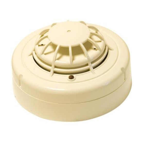
Figure 3: FD-851HTE, FD-851RE
and FD-851TE Thermal Detectors
DETECTOR COVER
THERMAL
DETECTOR
CHAMBER
COVER
DETECTOR
BASE
© System Sensor 2007
I56-1730-014
Werbung

Verwandte Anleitungen für Honeywell NOTIFIER FD-851RE


Inhaltszusammenfassung für Honeywell NOTIFIER FD-851RE
- Seite 1 0832 CAUTION FD-851TE: 0832-CPD-0191 FD-851RE: 0832-CPD-0089 Dust covers are fitted to the detectors to help protect units during shipment and when first installed. They are not intended to FD-851HTE: 0832-CPD-0088 provide complete protection against contamination; therefore detectors should be removed before beginning construction, major re-decoration or other dust producing activity.
- Seite 2 0832 CAUTELA FD-851TE: 0832-CPD-0191 FD-851RE: 0832-CPD-0089 Ai rivelatori è applicato un parapolvere che previene possibili danneggiamenti causati dal trasporto e limita l’ingresso nel rivelatore FD-851HTE: 0832-CPD-0088 della polvere che si può creare nel momento dell’installazione. Questa protezione è ad ogni modo limitata; i rivelatori dovrebbero essere rimossi prima di iniziare interventi di ristrutturazione, costruzione od altre attività...
- Seite 3 0832 PRECAUCIÓN FD-851TE: 0832-CPD-0191 FD-851RE: 0832-CPD-0089 Los detectores se suministran con una tapa para protegerlos del polvo durante el transporte y etapa inicial de la instalación. No se FD-851HTE: 0832-CPD-0088 pretende que estas tapas ofrezcan protección total contra todo tipo de contaminación; por ello, antes de iniciarse cualquier trabajo de construcción, decoración u otra actividad que genere polvo, los detectores deben ser retirados.
- Seite 4 0832 ACHTUNG FD-851TE: 0832-CPD-0191 Der Melder ist werkseitig mit einem Staubschutz vor Verschmutzung während des Transportes oder der Erstinstallation geschützt. FD-851RE: 0832-CPD-0089 Ein vollständiger Schutz gegen eine Verunreinigung ist dadurch nicht gewährleistet. Deshalb sollten die Melder vor Beginn von FD-851HTE: 0832-CPD-0088 Konstruktions-, umfangreichen Dekorationsarbeiten oder sonstigen Aktivitäten mit Staubentwicklung entfernt werden.