
Verwandte Anleitungen für Pioneer gm d 515


Inhaltszusammenfassung für Pioneer gm d 515
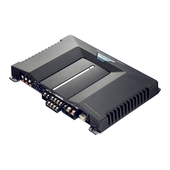
- Seite 1 5 channel power amplifier Amplificateur de puissance à cinq voies Owner’s Manual GM-D515 Mode d’emploi...
-
Seite 2: Inhaltsverzeichnis
Contents Before Using This Product ...... 2 Connecting the Unit ........5 In case of trouble ..........2 Connection Diagram ........6 About This Product .......... 2 Connecting the Power Terminal ......7 CAUTION ............2 Connecting the Speaker Output Terminals ..8 WARNING ............ -
Seite 3: Before Using This Product
Before Using This Product Thank you for purchasing this PIONEER WARNING product. Before attempting operation, be • Always use the special red battery and ground sure to read this manual. wires ([RD-223] × 2), which are sold separately. Connect the battery wire directly to the car bat-... -
Seite 4: Setting The Unit
• When using with an RCA equipped car stereo (standard output of 500 mV), set to the NORMAL position. When using with an RCA equipped Pioneer car stereo with max. output of 4 V or more, adjust level to match the car stereo output level. -
Seite 5: Power Indicator
Power Indicator The power indicator lights when the power is switched on. HPF (High-Pass Filter) Select Switch (CH A and CH B) Set the HPF select switch as follows according to the type of speaker that is connected to the speaker output connector and the car stereo system: HPF Select Audio frequency range... -
Seite 6: Connecting The Unit
Connecting the Unit CAUTION • Disconnect the negative (–) terminal of the bat- • Make sure that wires will not interfere with mov- tery to avoid the risk of short-circuit and damage ing parts of the vehicle, such as the gearshift, to the unit. -
Seite 7: Connection Diagram
Connection Diagram Ground wire (Black) [RD-223] (sold separately) Connect to metal body or chassis. Fuse (30 A) × 2 Special red battery wire [RD-223] (sold separately) After making all other connections at the amplifier, connect the battery wire terminal of the amplifier to the positive (+) terminal of the battery. -
Seite 8: Connecting The Power Terminal
Connecting the Unit Connecting the Power Terminal 3. Attach lugs to wire ends. Lugs not supplied. • Always use the special red battery and ground • Use pliers, etc., to crimp lugs to wires. wires ([RD-223] × 2), which are sold separately. Connect the battery wire directly to the car bat- tery positive terminal (+) and the ground wire to the car body. -
Seite 9: Connecting The Speaker Output Terminals
Connecting the Speaker Output 3. Connect the speaker wires to the speaker output terminals. Terminals • Fix the speaker wires securely with the termi- nal screws. 1. Expose the end of the speaker wires Terminal screw using nippers or a cutter by about 10 mm and twist. -
Seite 10: Connecting The Speaker Wires
4 Ohm Installation 2 Ohm Installation 2 Ohm Installation 1 Ohm Installation DO NOT install or use your Pioneer DO NOT install or use your Pioneer amplifier by wiring speakers rated at 4 amplifier by wiring speakers rated at 2... - Seite 11 Connect the speaker leads according to the figures shown below. (Left) Speaker output terminal Speaker output A (Right) RCA input jack A (CH A) + + + + RCA input jack B (Right) (CH B) Speaker output B RCA input jack SUB (Left) (CH SUB) Subwoofer output...
-
Seite 12: Installation
Installation the surface of any attached speakers could become hot to the touch and minor burns could CAUTION result. • Do not install in: • Do not install the amplifier on unstable places —Places where it could injure the driver or pas- such as the spare tire board. -
Seite 13: Specifications
Specifications Power source ......................14.4 V DC (10.8 — 15.1 V allowable) Grounding system ............................Negative type Current consumption ....................43.8 A (at continuous power, 4 Ω) Average current drawn* ...................... 10.9 A (4 Ω for five channels) Fuse ..................................25 A × 3 Dimensions ........................ - Seite 14 Contenido Antes de usar este producto ....2 Conexión de la unidad ......5 En caso de desperfectos ........2 Diagrama de conexión ........6 Sobre este producto .......... 2 Conexión del terminal de alimentación .... 7 PRECAUCIÓN ..........2 Conexión del terminal de salida de altavoz ..
-
Seite 15: Antes De Usar Este Producto
Antes de usar este producto Muchas gracias por la adquisición de este ADVERTENCIA producto PIONEER. Antes de tratar de operarlo, lea atentamente este manual. • Siempre utilice el cable de batería rojo especial y los cables de tierra ([RD-223] × 2), vendidos sep- aradamente. -
Seite 16: Ajuste De Esta Unidad
RCA (salida estándar de 500 mV), ajuste a la posición NORMAL. Cuando use con un estéreo de automóvil Pioneer equipado con RCA con una salida máxima de 4 V o más, ajuste el nivel para adecuarse al nivel de salida del estéreo del automóvil. -
Seite 17: Indicador De Alimentación
Indicador de alimentación El indicador de alimentación se ilumina cuando la unidad se encuentra activada. Interruptor de selección HPF (Filtro de paso alto) (CH A y CH B) Ajuste el interruptor de selección HPF de la manera siguiente, de acuerdo al tipo de altavoz que se encuentra conectado al conector de salida de altavoz y al sistema estéreo de automóvil: Interruptor de... -
Seite 18: Conexión De La Unidad
Conexión de la unidad PRECAUCIÓN • Quite el terminal negativo (–) de la batería para • No corte ningún cable. De otra manera, el circuito evitar riesgo de cortocircuitos y daño a la unidad. de protección podría no funcionar cuando •... -
Seite 19: Diagrama De Conexión
Diagrama de conexión Cable de puesta a tierra (negro) [RD-223] (en venta por separado) Conecte a una carrocería metálica o chasis. Fusible (30 A) × 2 Cable de batería rojo especial [RD-223] (en venta por separado) Después de realizar todas las conexiones al amplificador, conecte el terminal del conductor de batería del amplifi- cador al terminal positivo (+) de la batería. -
Seite 20: Conexión Del Terminal De Alimentación
Conexión de la unidad Conexión del terminal de 3. Fije las orejetas a los extremos de los cables. Orejetas no suministra- alimentación dos. • Siempre utilice el cable de batería rojo especial y • Utilice alicates, etc. para plegar las orejetas a los cables de tierra ([RD-223] ×... -
Seite 21: Conexión Del Terminal De Salida De Altavoz
Conexión del terminal de salida 3. Conecte los cables de altavoz al ter- minal de salida de altavoz. de altavoz • Fije los cables firmemente utilizando los tornillos para terminales. 1. Desnude la extremidad de los cables de altavoces utilizando alicates o Torrillo de terminal una tajadera por aproximadamente 10 mm y tuérzala. -
Seite 22: Conexión De Los Cables De Altavoces
Instalación de 1 ohmio NO instale ni utilice su amplificador NO instale ni utilice su amplificador Pioneer mediante la conexión de altavoces Pioneer mediante la conexión de altavoces de 4 ohmios nominales (o menos) en de 2 ohmios nominales (o menos) en... - Seite 23 Conecte los cables de altavoz según los diagramas mostrados abajo. (Izquierdo) Terminal de salida de altavoz Salida de altavoz A Tomas de conector de (Derecho) entrada RCA A (CH A) + + + + Tomas de conector de entrada RCA B (CH B) (Derecho) Salida de altavoz B Tomas de conector de entrada...
-
Seite 24: Instalación
Instalación la superficie del amplificador y la superficie de cualquier altavoz instalado también podrían po- PRECAUCIÓN nerse muy calientes al tacto, pudiendo causar • No lo instale en: pequeñas quemaduras. —Donde podría lesionar al conductor o a los • No instale el amplificador sobre superficies pasajeros si se detiene el vehículo brusca- inestables como el tablero del neumático de mente. -
Seite 25: Especificaciones
Especificaciones Alimentación ......................14,4 V CC (10,8 — 15,1 V permisible) Sistema de puesta a tierra ..........................Tipo negativo Consumo de corriente ...................... 43,8 A (potencia continua, 4 Ω) Consumo de corriente promedio* ..................10,9 A (4 Ω para cinco canales) Fusible .................................. - Seite 26 Inhaltsverzeichnis Vor Gebrauch dieses Produkts ....2 Anschluss der Einheit ......5 Im Störungsfall ..........2 Anschlussschema ..........6 Über dieses Produkt .......... 2 Anschluss der Stromversorgung ......7 VORSICHT ............2 Anschluss der Lautsprecher-Ausgang- WARNUNG ............2 Klemmen ............ 8 Anschließen der Lautsprecherkabel ....
-
Seite 27: Vor Gebrauch Dieses Produkts
Vor Gebrauch dieses Produkts Vielen Dank für den Kauf dieses WARNUNG PIONEER Produkts. Diese Bedienungsanleitung vor der • Verwenden Sie nur getrennt erhältliche rote Spezial-Batterie- und Massekabel ([RD-223] × 2). Inbetriebnahme sorgfältig durchlesen. Das Batteriekabel direkt an den Pluspol (+) der Wagenbatterie und das Massekabel an Im Störungsfall... -
Seite 28: Einstellen Dieses Geräts
• Bei Gebrauch mit einer mit RCA ausges- tatteten Auto-Stereoanlage (Standard- Ausgang 500 mV) auf die Position NOR- MAL einstellen. Bei Gebrauch mit einer mit RCA ausgestatteten Pioneer-Auto- Stereoanlage mit einem maximalen Ausgang von 4 V oder mehr den Pegel dem Auto-Stereoanlagen-Ausgangspegel anpassen. -
Seite 29: Stromanzeige
Stromanzeige Die Stromanzeige leuchtet auf, wenn die Stromversorgung eingeschaltet wird. HPF (Hochpassfilter)-Wahlschalter (CH A und CH B) Stellen Sie den HPF-Wahlschalter wie in folgendem Diagramm beschrieben ein, in Abhängigkeit von dem Lautsprechertyp der am Lautsprecher-Ausgangsanschluss und dem Fahrzeugstereo-System vorhanden ist: HPF- Wahl- Auszugebender Audio- Lautsprecher-... -
Seite 30: Anschluss Der Einheit
Anschluss der Einheit VORSICHT • Trennen Sie das Batterieanschlusskabel vom • Kürzen Sie die Kabel nicht. Gekürzte Kabel negativen (–) Batteriepol, um Kurzschlüsse und können einen Ausfall der Schutzschaltung Schäden am Gerät zu vermeiden. verursachen. • Befestigen Sie die Kabel mit Kabelklemmen oder •... -
Seite 31: Anschlussschema
Anschlussschema Erdungskabel (schwarz) [RD-223] (separat erhältlich) An Fahrzeugkarosserie oder Metallteil anschließen. Sicherung (30 A) × 2 Spezielles rotes Batteriekabel [RD-223] (separat erhältlich) Nachdem alle anderen Anschlüsse am Verstärker ausgeführt worden sind, das Batterie-Kabelklemme des Verstärkers mit der positiven (+) Klemme der Batterie verbinde. -
Seite 32: Anschluss Der Stromversorgung
Anschluss der Einheit Anschluss der Stromversorgung 3. Bringen Sie Kabelschuhe an den Kabelenden an. Kontaktzungen • Verwenden Sie nur getrennt erhältliche rote nicht mitgeliefert. Spezial-Batterie- und Massekabel ([RD-223] × 2). Das Batteriekabel direkt an den Pluspol (+) der • Mit einer Zange o.Ä. die Kontaktzungen am Wagenbatterie und das Massekabel an Draht festklemmen. -
Seite 33: Anschluss Der Lautsprecher-Ausgang-Klemmen
Anschluss der Lautsprecher- 3. Schließen Sie die Lautsprecher- kabel an die Lautsprecheraus- Ausgang-Klemmen gangklemmen an. • Die Lautsprecherdrähte fest mit den 1. Die Enden der Lautsprecherkabel Klemmenschrauben befestigen. um ca. 10 mm mit einer Kneifzange oder einem Schneider abisolieren Klemmenschraube und die Kabelenden zusammen- drehen. -
Seite 34: Anschließen Der Lautsprecherkabel
4-Ω-Lautsprecher pro Kanal. einzelnen 2-Ω-Lautsprecher pro Kanal. Wenden Sie sich mit allen Fragen bitte an Wenden Sie sich mit allen Fragen bitte an Ihren Pioneer-Händler oder rufen Sie den Ihren Pioneer-Händler oder rufen Sie den Pioneer-Kundenservice an. Pioneer-Kundenservice an. - Seite 35 Schließen Sie die Lautsprecherkabel gemäß folgenden Abbildungen an. Lautsprecher (Links) Ausgangklemme Lautsprecher-Ausgang A (Rechts) RCA-Eingangsbuchsen A (CH A) + + + + RCA-Eingangsbuchsen B (Rechts) (CH B) Lautsprecher-Ausgang B RCA-Eingangsbuchsen SUB (Links) (CH SUB) Subwoofer-Ausgang Ein-/Ausgangskombination Eingang Ausgang Eingang Ausgang CH A CH A CH A...
-
Seite 36: Einbau
Einbau Folge sein. Berührung mit Flüssigkeiten kann auch zu einer Beschädigung von Verstärker und VORSICHT Lautsprechern, sowie zu Rauchbildung und Über- • Keinesfalls an Orten einbauen: hitzung führen. Außerdem können Oberflächen von —Plätze, an denen sich der Fahrer oder die Verstärker und jeglicher angebrachter Lautsprecher Fahrzeuginsassen bei plötzlichem Abbremsen heiß... -
Seite 37: Technische Daten
Technische Daten Stromversorgung.................. 14,4 V Gleichspannung (Toleranz 10,8 — 15,1 V) Erdungssystem ................................ Negativ Leistungsaufnahme ..................43,8 A (bei gleichbleibendem Strom, 4 Ω) Durchschnittliche Stromentnahme* ..................10,9 A (4 Ω für Fünf-Kanal) Sicherung ................................25 A × 3 Abmessungen ........................350 (B) × 52 (H) × 268 (T) mm Gewicht ........................ - Seite 38 Table des matières Avant d’utiliser cet appareil ....2 Raccordement de l’appareil ....5 En cas d’anomalie ..........2 Schéma de raccordement ........6 Quelques mots concernant Raccordement de la borne d’alimentation ..7 cet appareil ..........2 Raccordement des bornes de sortie vers PRÉCAUTION ..........
-
Seite 39: Avant D'utiliser Cet Appareil
Avant d’utiliser cet appareil Nous vous remercions d’avoir acheté cet ATTENTION appareil PIONEER. Avant de l’utiliser, prendre soin de lire ce manuel. • Utilisez le câble rouge et le câble de masse ([RD- 223] × 2) qui sont vendus séparément. Reliez le câble rouge à... -
Seite 40: Réglage De L'appareil
B et de la commande de niveau des graves (CH SUB) permet d’adapter la sortie de l’autoradio à l’amplificateur Pioneer. En principe, placez ces com- mandes sur la position “NORMAL (NORM.)”. Si le niveau d’écoute est faible même lorsque la commande de l’autoradio est sur la position correspon-... -
Seite 41: Témoin D'alimentation
Témoin d’alimentation Ce témoin s’éclaire lorsque l’amplifica- teur est sous tension. Sélecteur HPF (Filtre passe-haut) (CH A et CH B) Positionnez le sélecteur HPF comme indiqué ci-dessous en tenant compte de l’autoradio et du type du haut-parleur relié au connecteur de sortie. Sélecteur Gamme des fréquences Type de haut-... -
Seite 42: Raccordement De L'appareil
Raccordement de l’appareil PRÉCAUTION • Pour éviter tout risque de court-circuit ou • Veillez à ce qu’aucun câble ne soit en court- d’endommager cet appareil, débranchez le câble circuit, faute de quoi le circuit de protection relié à la borne négative (–) de la batterie, au pourrait être dans l’incapacité... -
Seite 43: Schéma De Raccordement
Schéma de raccordement Câble de masse (noir) [RD-223] (vendu séparément) Reliez ce câble à la carrosserie du véhicule. Fusible (30 A) × 2 Câble rouge de liaison à la batterie [RD-223] (vendu séparément) Après avoir effectué tous les autres raccordements de l’amplificateur, reliez ce câble à... -
Seite 44: Raccordement De La Borne D'alimentation
Raccordement de l’appareil Raccordement de la borne 3. Fixez une cosse à l’extrémité de chaque câble. Les cosses ne sont pas d’alimentation fournies. • Utilisez le câble rouge et le câble de masse ([RD- • Utilisez un outil spécial, etc., pour sertir la 223] ×... -
Seite 45: Raccordement Des Bornes De Sortie Vers Les Haut-Parleurs
Raccordement des bornes de 3. Reliez les câbles de liaisons aux haut-parleurs aux bornes de sortie sortie vers les haut-parleurs vers les haut-parleurs. • Serrez soigneusement les cosses au moyen 1. Dénudez l’extrémité des câbles de des vis. liaison aux haut-parleurs par une Vis de borne pince ou un couteau sur 10 mm environ et torsadez les brins des... -
Seite 46: Connexion Des Câbles Des Haut-Parleurs
Configuration 1 Ohm NE PAS installer ni utiliser l’amplificateur NE PAS installer ni utiliser l’amplificateur Pioneer câblé sur des haut-parleurs de 4 Pioneer câblé sur des haut-parleurs de 2 Ohms (ou moins) en parallèle pour obtenir Ohms (ou moins) en parallèle pour obtenir une impédance de 2 Ohms (ou moins) pour... - Seite 47 Connecter les fils du haut-parleur suivant les figures cidessous. (Gauche) Borne de sortie vers un haut-parleur Sortie de haut-parleur A (Droite) Prises d’entrée A Cinch (RCA) (CH A) + + + + Prises d’entrée B Cinch (Droite) (RCA) (CH B) Sortie de haut-parleur B Prises d’entrée SUB (Gauche)
-
Seite 48: Installation
Installation De plus, le contact avec un liquide pourrait endommager l’amplificateur et les enceintes, pro- PRÉCAUTION duire de la fumée ou surchauffer l’appareil. Enfin, • N’installez pas l’appareil: la surface de l’amplificateur et des enceintes con- —dans un endroit où il pourrait blesser un occu- nectées peut devenir chaude au toucher et entraîn- pant du véhicule en cas d’arrêt brusque;... -
Seite 49: Caractéristiques Techniques
Caractéristiques techniques Alimentation ........................ 14,4 V CC (10,8 — 15,1 V permis) Mise à la masse .......................... Pôle négatif de la batterie Consommation de courant ..................43,8 A (à la puissance continue, 4 Ω) Consommation moyenne de courant* .................. 10,9 A (4 Ω pour cinq voies) Fusible .................................. - Seite 50 Indice Prima di usare questo prodotto ....2 Come collegare I’unità ......5 In caso di difficotà ..........2 Schema di collegamento ........6 A proposito del prodotto ........2 Come collegare il terminale ATTENZIONE ..........2 dell’alimentazione ........7 ATTENZIONE ..........
-
Seite 51: Prima Di Usare Questo Prodotto
Prima di usare questo prodotto Grazie per aver acquistato questo prodotto ATTENZIONE PIONEER. Leggere attentamente queste istruzioni prima di usare questo apparec- • Usare sempre lo speciale cavo rosso per batteria chio. ed i cavi di messa a terra (2 di tipo [RD-223]) venduti a parte. -
Seite 52: Regolazione Di Questa Unità
A e B e del comando del livello dei bassi (CH SUB) aiuta ad adeguare l’us- cita dell’unità stereo all’amplificatore Pioneer. Normalmente impostare questi comandi sulla posizione “NORMAL (NORM.)”. Se l’uscita risulta bassa anche alzando il volume dello stereo, ruotare questi comandi in senso orario. -
Seite 53: Indicatore Dell'alimentazione
Indicatore dell’alimentazione L’indicatore dell’alimentazione viene illu- minato quando si attiva l’alimentazione. Selettore HPF (filtro passa-alto) (CH A e CH B) Regolare il selettore HPF come segue a secondo del tipo di altoparlante collegato al connet- tore di uscita dell’altoparlante ed il sistema d’impianto stereo per macchina: Selettore Gamma della frequenza Tipo di... -
Seite 54: Come Collegare I'unità
Come collegare l’unità ATTENZIONE • Togliere il contatto negativo (–) dalla batteria per • Non cortocircuitare i cavi. In caso contrario, il evitare ogni rischio di cortocircuito e danni all’u- circuito di protezione non funzionerà quando sarà nità. necessario. • Fissare il cablaggio con dei fermi per cavi oppure •... -
Seite 55: Schema Di Collegamento
Schema di collegamento Cavo di massa (nero) [RD-223] (venduto separatamente) Collegare alla parte metallica della carrozzeria oppure dello chassis. Fusibile (30 A) × 2 Cavo rosso speciale della batteria [RD-223] (venduto separatamente) Dopo aver eseguito tutti gli altri collegamenti all’amplifica- tore, collegare il terminale del cavo dell’amplificatore des- tinato alla batteria al terminale positivo (+) della batteria. -
Seite 56: Come Collegare Il Terminale Dell'alimentazione
Come collegare l’unità Come collegare il terminale 3. Applicare degli spinotti alle estrem- ità dei cavi. I capicorda non sono dell’alimentazione forniti. • Usare sempre lo speciale cavo rosso per batteria • Usare le pinze, ecc., per raggrinzire i capicor- ed i cavi di messa a terra (2 di tipo [RD-223]) da stringendoli ai cavi. -
Seite 57: Come Collegare Il Terminale Di Uscita Degli Altoparlanti
Come collegare il terminale di 3. Collegare i cavi degli altoparlanti al terminale di uscita degli altoparlanti. uscita degli altoparlanti • Fissare saldamente i cavi con le viti per morsetti. 1. Utilizzando delle pinze oppure una Vite del terminale tagliatrice esporre l’estremità dei cavi di altoparlanti per circa 10 mm e torcerla. -
Seite 58: Collegamento Dei Cavi D'altoparlanti
Installazione da 1 Ohm NON installate od utilizzate l’amplificatore NON installate od utilizzate l’amplificatore Pioneer collegando in parallelo ai canali A e Pioneer collegando in parallelo al canale del B diffusori con impedenza da 4 Ohm o subwoofer diffusori con impedenza da 2 meno al fine di ottenere un’impedenza di... - Seite 59 Collegare i fili dell’altoparlante in base alle seguenti illustrazioni. Terminale di uscita degli (Sinistra) altoparlanti Uscita altoparlante A (Destra) Prese di ingresso A tipo RCA + + + + (CH A) Prese di ingresso B tipo RCA (Destra) (CH B) Uscita altoparlante B Prese di ingresso SUB tipo RCA (Sinistra)
-
Seite 60: Installazione
Installazione superficie dell’amplificatore o quella degli altoparlanti ad esso collegati potrebbe inoltre ATTENZIONE divenire molto calda e, al contatto, procurare • Non installare l’unità sulle posizioni seguenti: piccole scottature. —Posti dove potrebbe ferire il conducente o i • Non installare l’amplificatore in luoghi instabili passaggeri se il veicolo si arresta brusca- come il pannello della ruota di scorta. -
Seite 61: Caratteristiche
Caratteristiche Alimentazione....................14,4 V C.C. (10,8 — 15,1 V permissìbile) Collegamento a terra ............................. Tipo negativo Consumo ......................43,8 A (ad alimentazione continua, 4 Ω) Corrente media consumata* ....................10,9 A (4 Ω per cinque canali) Fusibile .................................. 25 A × 3 Dimensioni ........................ - Seite 62 Inhoudsopgave Alvorens gebruik ........2 Aansluiten van het toestel ...... 5 Bij problemen ............ 2 Aansluitschema ..........6 Over dit product ..........2 Aansluiten van het spanningsaansluitpunt ..7 WAARSCHUWING ........2 Verbinden van de luidspreker- WAARSCHUWING ........2 uitgangsaansluitingen ........ 8 Aansluiten van de luidsprekerdraden ....
-
Seite 63: Alvorens Gebruik
Alvorens gebruik Dank U zeer voor de aanschaf van dit WAARSCHUWING PIONEER-product. Lees deze gebruiks- aanwijzing goed door, voordat het toestel • Gebruik altijd de los verkrijgbare, speciale rode accu- en aardedraden ([RD-223] × 2). Verbind in gebruik genomen wordt. -
Seite 64: Instellen Van Dit Toestel
(CH SUB) instellen in overeenstemming met de uitgangssig- nalen van de auto-stereo naar de Pioneer versterker. Zet deze regelaars normaliter in de “NORMAL (NORM.)” stand. Indien de weergave te zacht klinkt, zelfs... -
Seite 65: Spanningsindicator
Spanningsindicator De spanningsindicator licht op wanneer de spanning wordt ingeschakeld. HPF (hoge-doorlaatfilter)-keuzeschakelaar (CH A en CH B) Stel de HPF-keuzeschakelaar als volgt in, naargelang het type luidspreker dat is aangesloten op de luidsprekeruitgangsaansluiting en het autostereosysteem: HPF-keuze- Uit te voeren Type Opmerkingen schakelaar... -
Seite 66: Aansluiten Van Het Toestel
Aansluiten van het toestel WAARSCHUWING • Voorkom kortsluiting en beschadiging van de • Sluit draden niet kort. Het beschermingscircuit eenheid en ontkoppel de nagatieve (–) accupool werkt anders namelijk niet wanneer het voor de van het voertuig. veiligheid zou moeten functioneren. •... -
Seite 67: Aansluitschema
Aansluitschema Aardingssnoer (zwart) [RD-223] (los verkrijgbaar) Sluit dit snoer aan op de carrosserie of het chassis. Zekering (30 A) × 2 Speciaal rood accusnoer [RD-223] (los verkrijgbaar) Sluit, nadat alle andere aansluitingen op de versterk- er zijn gemaakt, het accusnoer-aansluitpunt van de versterker aan op het positieve aansluitpunt (+) van de accu. -
Seite 68: Aansluiten Van Het Spanningsaansluitpunt
Aansluiten van het toestel Aansluiten van het 3. Bevestig verbindingsstukjes aan de uiteinden van de draden. De spanningsaansluitpunt verbindingsstukjes zijn niet • Gebruik altijd de los verkrijgbare, speciale rode bijgeleverd. accu- en aardedraden ([RD-223] × 2). Verbind • Klem de verbindingsstukjes met een tangetje het accudraad direct met de positieve pool (+) van aan de draden. -
Seite 69: Verbinden Van De Luidspreker- Uitgangsaansluitingen
Verbinden van de luidspreker- 3. Verbind de luidsprekerdraden met de luidsprekeruitgangsaansluiting. uitgangsaansluitingen • Zet de luidsprekerdraden goed met de schroeven van de aansluiting vast. 1. Verwijder ongeveer 10 mm isolatie Aansluitpuntschroef van het uiteinde van de luidspreker- draden met een tang, en draai de draadstrengen ineen. -
Seite 70: Aansluiten Van De Luidsprekerdraden
4 Ohm installatie 2 Ohm installatie 2 Ohm installatie 1 Ohm installatie Installeer of gebruik uw Pioneer versterker Installeer of gebruik uw Pioneer versterker NIET door luidsprekers van 4 Ohm (of NIET door luidsprekers van 2 Ohm (of lager) parallel te schakelen om zo een... - Seite 71 Sluit de luidsprekersnoeren aan zoals aangegeven in de onderstaande afbeeldingen. (Links) Luidspreker Luidspreker uitgang A uitgang aansluiting (Rechts) RCA-ingangspenaansluiting A (CH A) + + + + RCA-ingangspenaansluiting B (Rechts) (CH B) Luidspreker uitgang B RCA-ingangspenaansluiting SUB (Links) (CH SUB) Subwoofer uitgang Combinaties van in- en uitgangsaansluitingen Ingang Uitgang...
-
Seite 72: Installatie
Installatie luidsprekers kunnen ook beschadigd raken, rook produceren en oververhit raken door contact met WAARSCHUWING vloeistoffen. Daarbij kan het oppervlak van de • Niet installeren op: versterker en het oppervlak van aangesloten —Plaatsen waar het de bestuurder of passagiers luidsprekers heet worden, hetgeen kan leiden tot zou kunnen verwonden wanner de auto lichte brandwonden. -
Seite 73: Technische Gegevens
Technische gegevens Spanningsbron ..................14,4 V gelijkstroom (10,8 — 15,1 V toelaatbaar) Aarding ............................Negatieve klem aan massa Stroomverbruik ......................43,8 A (met continu spanning, 4 Ω) Gemiddeld stroomverbruik* ....................10,9 A (4 Ω voor vijf kanalen) Zekering .................................. 25 A × 3 Afmetingen ........................ - Seite 74 300 Allstate Parkway, Markham, Ontario L3R OP2, Canada Copyright © 2004 by Pioneer Corporation. TEL: 1-877-283-5901 All rights reserved. PIONEER ELECTRONICS DE MEXICO, S.A. de C.V. Publication de Pioneer Corporation. Blvd.Manuel Avila Camacho 138 10 piso Copyright © 2004 Pioneer Corporation.