Werbung
Verfügbare Sprachen
Verfügbare Sprachen
Quicklinks
This manual is intended as a quick reference installation guide. Please refer to the control panel
manufacturers installation manual for detailed system information
GENERAL INFORMATION
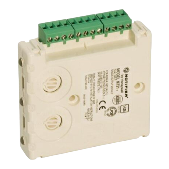
The M700 series of modules are a family of microprocessor controlled interface devices
permitting the monitoring and/or control of auxiliary devices.
SPECIFICATIONS
Operating Voltage Range
Maximum Standby Current (µA)
No Communications
Comm. LED blink enabled - 5 sec
Read 16 sec. LED blink 8 sec
LED Current (Red)
LED Current (Yellow)
Maximum rated continuous current with the switch closed (I
Maximum rated switching current (under short circuit) (I
Maximum leakage current (I
Maximum series impedance with the switch closed (Z
Operating Temperature
Humidity
Module Dimensions
Surface Mount Box Dimensions
Weight (Module Only)
Weight (Module and M200E-SMB)
Maximum Wire Gauge
INSTALLATION
Note:
These modules must only be connected to control panels using compatible proprietary
analogue addressable communication protocols for monitoring and control.
M700 series modules can be mounted in several ways (See figure 1):
1.
An M200E-SMB custom low profile surface-mounting box.
2.
An M200E-DIN Adaptor allows mounting onto standard 35mm x 7.5mm "Top Hat" DIN rail.
3.
An M200E-PMB Panel Mount Bracket allows the module to be mounted directly into a panel.
Wiring to all series M700 modules is via plug in type terminals capable of supporting conductors
up to 2.5mm²
Disconnect loop power before installing modules or sensors
The module address is selected by means of rotary decade address switches (see figure 2).
These can be accessed either from the front or the top of the module. A screwdriver should be
used to rotate the wheels to select the desired address, either from the front, or the top of the
module.
For modules having more than one channel, the address selected will refer to the first input
channel, the module will automatically assign the next one or two addresses as appropriate to the
second input channel and output channel. As a result, address 159 will be invalid for dual channel
modules, and addresses 158 and 159 are invalid for three channel modules. If these addresses
are selected, no response will be seen from the module. Note: Some control panels are only able
to use 99 addresses. If this is the case, 99 will be invalid for dual channel modules, and addresses
98 and 99 are invalid for three channel modules.
FIGURE 1: MODULE MOUNTING METHODS
M200E-SMB Surface Mount Box
COVER
MODULE
BASE BOX
FIGURE 3: M710 SINGLE INPUT AND M720 DUAL INPUT MODULE WIRING
LOOP OUTPUT
LOOP OUTPUT
LOOP INPUT
LOOP INPUT
LOOP OUTPUT (SEE NOTES 1)
47K
M200-EOL-R
Notes:
1
If short circuit isolation is not required, loop output+ should be wired to terminal 5 and not
2. Terminal 5 is internally connected to terminal 4.
2
The dashed line circuit connected to terminals 8 and 9 should only be used with the M720.
There are no connections to these terminals on the M710.
3
Provided the control panel is compatible, short circuit monitoring of the input circuit may
be possible. An 18KΩ resistor should be wired in series with each device switch being
monitored.
N200-91-01
Downloaded from
www.Manualslib.com
INSTALLATION INSTRUCTIONS FOR
M710 / M720 INPUT MODULES AND
M721 INPUT / OUTPUT MODULE
15 to 30VDC (Min 17.5VDC to ensure LED operation)
M710
M720
M721
310
340
340
510
600
660
410
440
440
2.2mA
8.8mA
max)
c
max)
s
max) with the switch open (isolated state)
L
max)
c
-20°C to 60°C
5% to 95% Relative Humidity
93mm(H) x 94mm(W) x 23mm(D)
132mm(H) x 137mm(W) x 40mm(D)
110 g
252 g
2.5mm²
CAUTION
TOP
Surface Mount Box
Base is affixed to
mounting surface, and
then the module and
cover are screwed
onto the base using the
two screws supplied.
-
+
-
+
M710 / M720
+
8 9
6 7
5
4
3
2
1
0
A
x10
47K
M200-EOL-R
(SEE NOTES 2)
Notifier UK Ltd. Charles Avenue, Burgess Hill, RH15 9UF
manuals search engine
Short Circuit Isolators
All M700 series modules are provided with short circuit monitoring and isolators on the intelligent
loop. If required the isolators may be wired out of the loop to facilitate the use of the modules on
high current loaded loops, for example if sounders are used. To achieve this, the loop out positive
should be wired to terminal 5 rather than terminal 2. See the relevant wiring diagram for details.
M710 SINGLE CHANNEL INPUT MODULE
Provides single channel monitoring of normally open contact fire alarm and supervisory devices.
The M710 has a single tri-colour green/red/yellow LED, which can be set by panel command to
pulse green each time the module is polled. In case of an alarm the panel can switch the red
indicator on continuously. The Yellow LED is controlled by the module and blinks to indicate an
open circuit on the input circuit. This fault indication is overridden by a panel command to turn the
red LED on.
M710 Wiring
See figure 3 for wiring details.
M720 DUAL CHANNEL INPUT MODULE
The M720 is a dual channel module used for the monitoring of normally open contact fire alarm
and supervisory devices.
It has two tri-colour LED's, one referring to each channel. Each LED can be set by panel
1A
command to pulse green each time the module channel is polled. In case of an alarm the panel
1A
can switch the red indicator on continuously. The Yellow LED is controlled by the module and
15mA
blinks to indicate an open circuit on the input circuit. This fault indication is always overridden by
130 m ohm at 15Vdc
a panel command to turn the red LED on.
M720 Wiring
See figure 3 for wiring details.
M721 DUAL INPUT, SINGLE OUTPUT MODULE
This module provides dual channel monitoring of normally open contact fire alarm and
supervisory devices, and also provides single pole changeover contacts for the control of auxiliary
devices such as fire shutters.
Three tri-colour LED's are provided to indicate the status of each channel.
LED's A and B refer to the two input channels. Each LED can be set by panel command to pulse
green each time the module channel is polled. In case of an alarm the panel can switch the red
indicator on continuously.
LED C refers to the output channel. The LED can be set by panel command to pulse green each
time the channel is polled. The LED will be switched continuously on Green by command from
the control panel when the relay contacts are in the energised state.
The M721 relay contact ratings are 30VDC, 2A or 30VAC, 0.5A (Resistive load).
M721 Wiring
See figure 4 for wiring details
When switching inductive loads, in order
to protect the module from surges
caused by back emf as the load is
switched, it is important to protect the
A diode with a reverse breakdown voltage
of at least ten times the circuit voltage (dc
applications only), or a varistor (ac or dc
applications) should be connected across
M200E-DIN DIN Rail Bracket
Push Module into
adaptor Bracket until it
clips into place.
Locate top clip over
DIN rail and rotate
bottom down to clip
into place.
BOTTOM
To Remove, lift up,
then rotate top away
from the rail.
FIGURE 4: M721 DUAL INPUT SINGLE OUTPUT MODULE WIRING
LOOP OUTPUT
LOOP OUTPUT
A B
LOOP OUTPUT (SEE NOTES 1)
1
0
8 9
6 7
10
11
5
12
4
3
13
2
14
1
15
0
B
x1
C
47K
M200-EOL-R
Notes:
1
If short circuit isolation is not required, loop output+ should be wired to terminal 5 and not 2.
Terminal 5 is internally connected to terminal 4.
2
Provided the control panel is compatible, short circuit fault monitoring of the input circuit may
be possible. An 18KΩ resistor should be wired in series with each device switch being
monitored.
1
WARNING:
relay contacts.
the load.
FIGURE 2: ROTARY DECADE
ADDRESS SWITCHES
M200E-PMB Panel Mount Bracket
Adaptor bracket is
mounted directly into
panel using 2 x M4
Pan head screws.
Module is pushed into
adaptor until it clips
into place.
-
+
-
LOOP INPUT
+
LOOP INPUT
+
47K
NC
C
NO
M200-EOL-R
RELAY CONTACT RATING:
30VDC 2A OR 30VAC, 0.5A
RESISTIVE LOAD
0786-CPD-20342 07 - M710, M720
0786-CPD-20343 07 - M721
EN54-17: 2005 and EN54-18: 2005
CONTACT
DIODE
+
(DC
ONLY)
OR
VARISTOR
A B
M721
1
0
7 8 9
8 9
6 7
10
6
11
5
5
4
4
12
3
3
13
2
2
14
1
1
0
15
0
A
x10
B
x1
C
Pittway Tecnologica S.r.l,
Via Caboto 19/3,
34147 Trieste, Italy
I56-2005-013
Werbung

Verwandte Anleitungen für Honeywell NOTIFIER M710


Inhaltszusammenfassung für Honeywell NOTIFIER M710
- Seite 1 Short Circuit Isolators INSTALLATION INSTRUCTIONS FOR All M700 series modules are provided with short circuit monitoring and isolators on the intelligent M710 / M720 INPUT MODULES AND loop. If required the isolators may be wired out of the loop to facilitate the use of the modules on M721 INPUT / OUTPUT MODULE high current loaded loops, for example if sounders are used.
- Seite 2 Isolatori di corto circuito ISTRUZIONI PER L' INSTALLAZIONE DI Tutti i moduli della serie M700 sono dotati di un dispositivo di monitoraggio e di isolatori di corto MODULI DI INGRESSO M710/M720, E DEL circuito sul loop intelligente. Se necessario, è possibile cablare gli isolatori al loop in modo da MODULO DI INGRES SO/USCITA M721 agevolare l'utilizzo dei moduli in loop ad alta corrente se, ad esempio, si utilizzano avvisatori...
- Seite 3 0786-CPD-20342 07 - M710, M720 Pittway Tecnologica S.r.l, 0786-CPD-20343 07 - M721 Via Caboto 19/3, EN54-17: 2005 and EN54-18: 2005 34147 Trieste, Italy N200-91-01 Honeywell Life Safety Iberia, S.L. C/ Pau Vila, 15-19, 08911 Badalona (Barcelona), Spain I56-2005-013 Downloaded from www.Manualslib.com manuals search engine...
- Seite 4 Isolator INSTALLATIONSANLEITUNG FÜR DIE Alle Module der Serie M700 sind mit einer Kurzschlussüberwachung und einem Isolator für die MODULE M710 / M720 UND M721 Ringleitung ausgerüstet. Falls erforderlich können die Isolatoren aus der Verdrahtung herausgenommen werden, z.B. wenn Signalgeber angeschlossen sind deren Stromversorgung über die spezielle Ringleitung erfolgt.