
Verwandte Anleitungen für Honeywell 041460.17


Inhaltszusammenfassung für Honeywell 041460.17
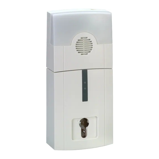
- Seite 1 Montage- und Bedienungsanleitung Tagalarm-Plus konventionell Art.-Nr. 041460.17 P02424-45-002-08 Änderungen EDOGU.01.0V03.xx vorbehalten 2015-02-04...
-
Seite 3: Inhaltsverzeichnis
Montage-Anschluss-Anleitung Tagalarm-Plus konventionell Inhalt Allgemeines ..............6 1.1 Einsatzmöglichkeiten . - Seite 4 Montage-Anschluss-Anleitung Tagalarm-Plus konventionell Bedienung und LED-Anzeigen ............24 6.1 Alarmauslösung .
-
Seite 5: Sicherheitshinweise
Montage-Anschluss-Anleitung Tagalarm-Plus konventionell In dieser Dokumentation werden folgende Symbole verwendet: Warnhinweis. Bezeichnet Gefahren für Mensch und/oder Gerät. Bei Nichtbeachtung droht Gefährdung für Mensch und/oder Gerät. Der Grad der Gefährdung wird durch das Warnwort gekennzeichnet: Vorsicht! Gefahr von Sach- und Umweltschäden. Warnung! Potentielle Gefahr, die zu leichten oder mittleren Körperverletzungen oder zu erheblichen Sachschäden führen kann. -
Seite 6: Allgemeines
Montage-Anschluss-Anleitung Tagalarm-Plus konventionell Allgemeines Einsatzmöglichkeiten Der Tagalarm-Plus konventionell dient zur Öffnungsüberwachung von Notausgangstüren. Das Gerät kann einfach vor Ort montiert werden. Es besteht die Möglichkeit, Bedieneinheit und Alarmierungseinheit getrennt voneinander oder kombiniert zu montieren. Somit kann entsprechend objektspezifischer oder anwendungstypischer Gegeben- heiten eine individuelle Montage erfolgen. -
Seite 7: Systemaufbau
Montage-Anschluss-Anleitung Tagalarm-Plus konventionell Systemaufbau Geräteaufbau Bedieneinheit 2.1.1 Übersicht LED grün LED rot Lötbrücke DIP-Schalter für Programmierung Deckelkontakt Bedienschalter für Schlüsselbedienung Befestigungsbohrungen Abreißsicherung Leitungseinführungen Leitungseinführung für 230 V AC Netzanschluss Zugentlastungen Kabelklammer für Leitungsführung Halteklammer und Ersatz-Halteklammer für Schließzylindermontage LEBENSGEFAHR durch spannungsführende Teile! 230 V AC Netzspannung! Vor dem Abnehmen des Gehäuseoberteils Netzspannung abschalten! -
Seite 8: Abreißkontakt
Montage-Anschluss-Anleitung Tagalarm-Plus konventionell 2.1.2 Abreißkontakt Der Abreißkontakt (Öse mit Litze), wird mit der mitgelieferten Schraube und der Distanzhülse direkt gegen den Montageuntergrund geschraubt. Je nach Montageuntergrund mit oder ohne Dübel. 2.1.3 Zugentlastung Mittels Kabelbinder können die Anschlussleitungen an der Zugentlastung befestigt werden. Beachten Sie die Hinweise zum Netz- anschluss in Kap. -
Seite 9: Abreißkontakt
Montage-Anschluss-Anleitung Tagalarm-Plus konventionell Montage Montagevarianten Das Gehäuse des Tagalarm-Plus besteht aus einer Bedien- und einer Alarmierungseinheit. Die Montage kann zusammen oder getrennt voneinander (z.B. Bedieneinheit neben der Tür, Alarmierungseinheit über der Tür) erfolgen. Zum Öffnen des Gehäuses sind die Gehäuseschrauben an der Ober-, bzw. Unterseite der Gehäuse zu lösen, anschließend kann jeweils das Geäuseoberteil abgenommen werden. -
Seite 10: Montage Bedieneinheit
Montage-Anschluss-Anleitung Tagalarm-Plus konventionell Montage Bedieneinheit 3.2.1 Montage direkt an der Wand Befestigen Sie das Gehäuse an den 3 Befestigungsbohrungen (A) auf einem festen Montageuntergrund. Für eine sichere Befestigung sollten die Schrauben dem Montageuntergrund angepasst sein. Je nach Montageuntergrund mit oder ohne Dübel. -
Seite 11: Montage Schlossabdeckung
Montage-Anschluss-Anleitung Tagalarm-Plus konventionell 3.2.4 Montage Schlossabdeckung Im Lieferumfang ist eine Schlossabdeckung enthalten. Falls zur Bedienung des Tagalarm-Plus konventionell nur ein externes Bedienteil (z.B. Schlüsseltaster) Verwendung findet. Entfernen Sie die Halteklammer vom Bedienschalter. Schlossabdeckung von vorne in die Öffnung für den Profilhalbzylinder in das Gehäuseoberteil einrasten. Korrekt eingerastete Schlossabdeckung. -
Seite 12: Montage Alarmierungseinheit
Montage-Anschluss-Anleitung Tagalarm-Plus konventionell Montage Alarmierungseinheit Befestigen Sie das Gehäuse an den 2 Befestigungsbohrungen auf einem festen Montageuntergrund. Für eine sichere Befestigung sollten die Schrauben dem Montageuntergrund angepasst sein. Je nach Monta- geuntergrund mit oder ohne Dübel. Ziehen Sie die Schrauben handfest Schrauben Sie die Abreißsicherung mit der mitgelieferten Schraube und der Distanzhülse direkt auf den Montageuntergrund. -
Seite 13: Informationen Zu Bedien- Und Programm-Funktionen
Montage-Anschluss-Anleitung Tagalarm-Plus konventionell Informationen zu Bedien- und Programm-Funktionen Nach dem Anlegen der Betriebsspannung ist der Tagalarm-Plus grundsätzlich im Aktivzustand. Aktivzustand bedeutet: ! Das Tagalarm-Gerät ist meldebereit - mit dem Öffnen der überwachten Tür wird ein Alarm ausgelöst. ! Durch Bedienung ist es möglich den Tagalam-Plus zeitbegrenzt, oder dauerhaft, in den inaktiven Zustand umzuschalten (nicht meldebereit). -
Seite 14: Türüberwachungs-Funktionen
Montage-Anschluss-Anleitung Tagalarm-Plus konventionell Türüberwachungs-Funktionen Die Programmierung erfolgt mittels den auf der Bedienplatine befindlichen 12 DIP-Schaltern. Durch die Kombination der DIP-Schalter DIP S6 und DIP S7 sowie DIP S9 und DIP S10 ergeben sich verschiedene Türüberwachungs- sowie Zustands- und Alarmfunktionen. Die DIP-Schalter müssen im spannungslosen Zustand eingestellt werden! Bitte beachten: Warten Sie vor dem erneuten Anlegen der Betriebsspannung ca. -
Seite 15: Dauerfreigabe Zeitbegrenzt "Sonderfunktion" - S9 = On
Montage-Anschluss-Anleitung Tagalarm-Plus konventionell 4.3.1.2 Dauerfreigabe zeitbegrenzt "Sonderfunktion" - S9 = ON: Unabhängig von den gewählten Parametrierfunktionen kann im inaktiven Zustand durch eine erneute Bedie- nung >3 s eine Einmalfreigabe erteilt werden. ! Innerhalb der Türfreigabezeit muss die Tür geöffnet werden (15s oder 60s wählbar). (Die manuelle Aktivschaltung, während der Türfreigabezeit, ist bei geschlossener Tür möglich.) ! Die Türoffenzeit ist unbegrenzt. -
Seite 16: Programmierungen Und Informationen Zur Türoffen-Erinnerung
Montage-Anschluss-Anleitung Tagalarm-Plus konventionell Programmierungen und Informationen zur Türoffen-Erinnerung Wird die Tür innerhalb der Türfreigabezeit geöffnet und bleibt offen, so wird parametrierabhängig eine akusti- sche Meldung ausgegeben (Türoffen-Erinnerung). Mit DIP-Schalter S6 erfolgt die Auswahl mit oder ohne Türoffen-Erinnerung und mit DIP-Schalter S7 die Art des Signals. Für den zeitlichen Ablauf der akustischen Erinnerung dient die Freigabezeit-Einstellung (15 s oder 60 s). -
Seite 17: Dauerfreigabe Ohne Erinnerungssignal
Montage-Anschluss-Anleitung Tagalarm-Plus konventionell 4.4.3 Dauerfreigabe ohne Erinnerungssignal: DIP S6 = OFF, DIP S7 = ON ! Mit der Inaktivschaltung wird die Tür bis zur manuellen Aktivschaltung freigegeben. ! Beliebiges Öffnen und Schließen der Tür ist erlaubt. Ablaufdiagramm: Dauerfreigabe ohne Erinnerungssignal 4.4.4 Dauerfreigabe mit Erinnerungssignal: DIP S6 = ON, DIP S7 = ON ! Mit der Inaktivschaltung wird die Tür bis zur manuellen Aktivschaltung freigegeben. -
Seite 18: Betrieb Im Verbund (Vernetzter Betrieb)
Montage-Anschluss-Anleitung Tagalarm-Plus konventionell Betrieb im Verbund (vernetzter Betrieb) Bei dieser Betriebsart ist es möglich, von einer zentralen Stelle alle im Verbund zusammengeschlossenen Tagalarmgeräte zu überwachen bzw. auch zu bedienen. Eine typische Anwendung ist z.B. im Marktleiter-Büro oder bei einem Pförtner / Hausmeister. Es können bis zu 16 Tagalarm-Plus konventionell im Verbund mit den unter Kap. -
Seite 19: Adresseinstellung Tagalarm-Plus Geräte
Montage-Anschluss-Anleitung Tagalarm-Plus konventionell 5.1.1 Adresseinstellung Tagalam-Plus Geräte Schalterstellung DIP-Schalter im Tagalarm-Plus konventionell DIP-Schalter Adresseinstellung Beginnend mit Adresse 1 (= 1. Tagalarm-Plus Gerät), muss jedem weiteren Tagalarm-Plus Gerät eine eigene Adresse zugewiesen wer- S1 bis S4 den. Somit können für 15 Tagalarm-Plus Geräte mit den DIP-Schal- tern 15 Adressen eingestellt werden. -
Seite 20: Adresseinstellung 16-Mg-Sperr- Und Anzeigemodul (Art.-Nr. 012542.17 / 012548.17)
Montage-Anschluss-Anleitung Tagalarm-Plus konventionell 5.1.2 Adresseinstellung 16-MG-Sperr- und Anzeigemodul (Art.-Nr. 012542.17 / 012548.17) Schalter DIP-Schalter im 16-MG Anzeigemodul DIP-Schalter Am 16-MG-Sperr- und Anzei- gemodul wird immer die S1 bis S6 im Adresse “0" programmiert. Sperr- und Anzeigemodul Rot-blinkende Anzeige-LEDs am Bedien- und Anzeigegerät weisen auf nicht vorhandene Teilnehmer bzw. -
Seite 21: Übersicht Der Tastenfunktion Am Bedien- Und Anzeigegerät
Montage-Anschluss-Anleitung Tagalarm-Plus konventionell 5.1.5 Übersicht der Tastenfunktion am Bedien- und Anzeigegerät Am Bedien- und Anzeigegerät kann über den Taster ne- ben dem Beschriftungsfeld das entsprechende Tagalarm- Gerät bedient werden. 5.1.6 Anschaltplan 16-MG-Sperr- und Anzeigemodul (Art.-Nr. 012542.17 / 012548.17) 5.1.7 Anschaltplan LED Bedienteil, weiß, für MB-Secure (Art.-Nr. 013000) 5.1.8 BUS-Anschluss Die BUS-Anschlussleitung ist als eine abgeschirmte, paarweise verseilte Leitung auszuführen. -
Seite 22: Bedien- Und Diagnose-Funktionen Am Bedien- Und Anzeigegerät
Montage-Anschluss-Anleitung Tagalarm-Plus konventionell Die Adernführung zwischen Tagalarm-Plus Gerät und einem Bedien- und Anzeigegerät ist nach dem neben angegebenen Schema auszuführen. 5.1.9 Beispielkonfiguration II Beispiel für einen Maximalausbau bei Vernetzung (16 Tagalarm-Plus Geräte): Sperr- und Anzeigemodul Anzahl Slave-Geräte (Adr.) Master-Gerät (Adr.) Adresse 0 15 Geräte = Adresse 1 bis 15 Programmierung “Master”, Einstel-... -
Seite 23: Led Bedienteil (Art.-Nr. 013000) Als Master
Montage-Anschluss-Anleitung Tagalarm-Plus konventionell 5.1.12 LED Bedienteil (Art.-Nr. 013000) als Master Beim LED Bedienteil (Art.-Nr. 013000) ist es alternativ möglich, diesem die Masterfunktion zuzuweisen. Vorteil: ! alle Tagalarm-Geräte haben eine eigene Adresse (15 Stück, keine Doppeladressierung). Dadurch besteht eine eindeutige Identifizierungsmöglichkeit. ! identische Diagnosefarben der LED's am LED Bedienteil wie beim Tagalarm-Plus: Rot zeigt eine Auslösung, grün die Türfreigabe und gelb eine Störung an. -
Seite 24: Bedienung Und Led-Anzeigen
Montage-Anschluss-Anleitung Tagalarm-Plus konventionell Bedienung und LED-Anzeigen Die Bedienung des Tagalarm-Gerätes kann nur von autorisierten Personen mittels Bedienung über den Schlüs- sel erfolgen. Des weiteren können externe Bedieneinheiten (z.B. Schlüsseltaster) angeschlossen sein. Alarmauslösung Wird im aktiven Zustand die Meldergruppe 2 (Eingang MG 2) ausgelöst (d.h. die überwachte Tür geöffnet), so wird unmittelbar ein örtlicher akustischer und optischer Alarm ausgelöst. -
Seite 25: Sabotageauslösung
Montage-Anschluss-Anleitung Tagalarm-Plus konventionell Sabotageauslösung Beide Gehäuseteile sind mit einem Deckel-, und Abreißkontakt ausgestattet. Wird die Sabotage-Meldergruppe ausgelöst (z.B. Gehäusedeckel wird abgehoben) so wird unmittelbar ein örtlicher akustischer und optischer Alarm ausgelöst. Die rote LED “Auslösung” blinkt im Verhältnis 1:1 bis die Ursache der Sabotageauslösung behoben ist. -
Seite 26: Technische Daten
-25 ° C bis +70 ° C Umweltklasse gemäß VdS Schutzart nach EN 60529 IP 40 Abmessungen Alarmeinheit B x H x T 110 x 103 x 53 mm Gehäusefarbe verkehrsweiß (ähnlich RAL 9016) Die EU-Konformitätserklärung steht unter "www.honeywell.com/security/de" im Service-/ Download- bereich zum Download bereit. -
Seite 27: Anschlusspläne
Montage-Anschluss-Anleitung Tagalarm-Plus konventionell Anschlusspläne Verdrahtung Bedieneinheit - Alarmeinheit... -
Seite 28: Anschlussplan Öffnungskontakt / Netzzuführung
Montage-Anschluss-Anleitung Tagalarm-Plus konventionell Anschlussplan Öffnungskontakt / 230 V AC Netzanschluss BUS: Anschluss zu weiteren Tagalarmgeräten (siehe Kap. 5.1). Anschluss des Öffnungskontakts der zu überwachenden Tür... -
Seite 29: Verwendung Von Duo Relaismodulen
Montage-Anschluss-Anleitung Tagalarm-Plus konventionell Verwendung von DUO Relaismodulen Zusätzliche potentialfreie Ausgänge (Schaltspannungen bis 230 V AC) können mit Relaismodulen zur Verfü- gung gestellt werden. 9.3.1 Tagalarm-Plus mit DUO Relaismodul Abgesetzt vom Tagalarmgerät können die beiden DUO- Re- laismodule (Art.-Nr. 010121.17,uP und Art.-Nr. 010131, aP), an beliebiger Stelle montiert werden. -
Seite 30: Bohrschablone
Montage-Anschluss-Anleitung Tagalarm-Plus konventionell Bohrschablone Maßangaben beachten, alle Maße in mm! Verbindungsteil bestimmt den Abstand der Gehäuse! - Seite 31 Montage-Anschluss-Anleitung Tagalarm-Plus konventionell...
- Seite 32 Honeywell Security Group Novar GmbH Johannes-Mauthe-Straße 14 D-72458 Albstadt P02424-45-002-08 2015-02-04 www.honeywell.com/security/de © 2015 Novar GmbH...
- Seite 33 Mounting and Operating Instructions Doorguard hardwired version Item no. 041460.17 P02424-45-002-08 Subject to change EDOGU.01.0V03.xx without notice 2015-02-04...
- Seite 35 Mounting and Operating Instructions Doorguard hardwired version Contents General ............... . 38 1.1 Range of application .
- Seite 36 Mounting and Operating Instructions Doorguard hardwired version Operation and LED indicators ............56 6.1 Alarm triggered .
-
Seite 37: Safety Instructions
Mounting and Operating Instructions Doorguard hardwired version The following general symbols will be used in the documentation: Warning sign Designates risks for man and/or machine. Non-compliance will create risks to man and/or machine. The level of risk is indicated by the word of warning: Caution! Risk of material and environmental damage. -
Seite 38: General
Mounting and Operating Instructions Doorguard hardwired version General Range of application The version of the Doorguard hardwired version monitors the opening of emergency exit doors and can be installed on site. The operating unit and alarm signalling device can be installed separately or in combination so that installation can be carried out according to the requirements of the premises or application in question. -
Seite 39: System Overview
Mounting and Operating Instructions Doorguard hardwired version System overview Device set up Operating unit 2.1.1 Overview LED green LED red Solder bridge DIP switch for programming Cover contact Operating switch for key operation Fixing holes Tear-off protection Cable entry Cable entry for 230 V AC mains supply Pull reliefs Cable clip for cable routing Retaining clip und spare part retaining clip... -
Seite 40: Tear-Off Contact
Mounting and Operating Instructions Doorguard hardwired version 2.1.2 Tear-off contact Screw the tear-off contact (eye with lead) directly to the mounting surface using the enclosed screw and spacer sleeve. Dowels may be necessary, depending on the mounting surface. 2.1.3 Pull-relief Use a cable binder to attach the connecting cables to the pull relief Observe the information on the mains supply in Chapter 7.1. -
Seite 41: Tear-Off Contact
Mounting and Operating Instructions Doorguard hardwired version 2.2.2 Tear-off contact Screw the tear-off contact (eye with lead) directly to the mounting surface using the enclosed screw and spacer sleeve. Dowels may be necessary, depending on the mounting surface. 2.2.3 Pull relief Use a cable binder to attach the connecting cables to the pull relief 2.2.4 Volume of reminder signal and acoustical alarm... -
Seite 42: Wall Mounting
Mounting and Operating Instructions Doorguard hardwired version Mounting operating unit 3.2.1 Wall mounting Attach the housing on the 3 fixing holes (A) on a firm mounting substrate. To fix securely, use screws that are suitable for the mounting surface in question. Depending on the mounting substrate, with or without dowel. -
Seite 43: Installation Lock Cover
Mounting and Operating Instructions Doorguard hardwired version 3.2.4 Installation lock cover The scope of delivery includes a lock cover that is used when ten Doorguard is to be operated with an external operating unit (e.g. Key switch). Disengage the retaining clip (see diagram below) from the operating switch. Lock in the lock cover into the upper part of the housing from the front side. -
Seite 44: Mounting Alarm Signalling Device
Mounting and Operating Instructions Doorguard hardwired version Mounting Alarm signalling device Attach the housing on the 2 fixing holes on a firm mounting substrate. To fix securely, use screws that are suitable for the mounting surface in question. Depending on the mounting substrate, with or without dowel. Tighten the screws finger-tight Screw the tear-off protection directly to the mounting surface using the enclosed screw and spacer sleeve. -
Seite 45: Information To Operating And Programm Functions
Mounting and Operating Instructions Doorguard hardwired version Information to operating and programm functions After switching the power supply the Doorguard hardwired version is in the activated state. Activated state means: ! If the door would opened, an optical and acoustical message are sent to alarm devices. ! Possible operating procedures for temporary or permanent release to set the Doorguard in the deactivated state. -
Seite 46: Door Open Monitoring
Mounting and Operating Instructions Doorguard hardwired version Door open monitoring Programming of the Doorguard takes place with the 12 DIP switches on the operating unit. By the combination of DIP switch DIP S6 and DIP S7 as well as DIP S9 and DIP S10 various door open monitoring states and alarm signalling modes are possible. -
Seite 47: Permanent Release With Automaticl Activation
Mounting and Operating Instructions Doorguard hardwired version 4.3.1.2 Permanent release with automatic activation "special function" - S9 = ON: Irrespective of parameterization when in deactivated state a operating >3 s switches the Doorguard in automa- tic activation (One time release). ! The door then has to be opened during the door release time (15 s or 60 s selectable). -
Seite 48: Programming Of Door Open Monitoring (Reminder Signal)
Mounting and Operating Instructions Doorguard hardwired version Programming of door open monitoring (reminder signal) Door open monitoring is meant to prevent the door from being left open by mistake. A signal sounds in good time before the door open time expires, indicating that the door should now be closed (Door open signal, re- minder signal). -
Seite 49: Permanent Release Without Door Open Signal
Mounting and Operating Instructions Doorguard hardwired version 4.4.3 Permanent release without door open signal: DIP S6 = OFF, DIP S7 = ON ! The Doorguard must be manually activated again. Activation is performed by way of manual operation using the key switch. ! The monitored door can be opened in the inactive state as often as required and for long as required. -
Seite 50: Network Operation (Linked Operation)
Mounting and Operating Instructions Doorguard hardwired version Network operation (linked operation) Network operation means that several Doorguards can be operated in a network. Example for this is the use in a head office or for the porter to remote control the doors. For the remote single indication of up to 16 Doorgu- ard hardwired version systems, a display module can be used as a remote indicating panel (master/slave operation) mentioned in Chapter 1.2. -
Seite 51: Address Setting Doorguard Hardwirder Version
Mounting and Operating Instructions Doorguard hardwired version 5.1.1 Address setting Doorguard hardwired version Switch position DIP switches in Doorguard hardwired version DIP switches Address setting Beginning with address 1 (= 1. Doorguard hardwired version device), every additional Doorguard hardwired version device must be allo- S1 to S4 cated its own address. -
Seite 52: Address Setting - 16-Dg Disable And Display Module (Item No. 012542.17 / 012548.17)
Mounting and Operating Instructions Doorguard hardwired version 5.1.2 Address setting - 16-DG disable and display module (Item no. 012542.17 / 012548.17) Switches DIP switches in 16-DG display module DIP switches The address "0" is always pro- grammed at the 16-DG dis- S1 to S6 in able and display module disable and... -
Seite 53: Overview Key Function At The Remote Indicating Panel
Mounting and Operating Instructions Doorguard hardwired version 5.1.5 Overview key function at the remote indicating panel With the corresponding key at the remote indicating panel the Doorguard can be remote controled. 5.1.6 Connection diagram 16-DG disable and display module (Item no. 012542.17 / 012548.17) 5.1.7 Connection diagram LED keypad, white, for MB-Secure (Item no. -
Seite 54: Configuration Example Ii
Mounting and Operating Instructions Doorguard hardwired version Route wires between the Doorguard hard- wired version device and remote indicating panel as shown in the diagram. 5.1.9 Configuration example II Example for maximum configuration in the event of networking (16 Doorguard hardwired versions): Remote and indicating panel Number of Slave-devices (Addr.) Master-device (Addr.) -
Seite 55: Led Keypad (Item No. 013000) As Master
Mounting and Operating Instructions Doorguard hardwired version 5.1.12 LED keypad (Item no. 013000) as master Only the LED keypad (Item no. 013000) is alternatively possible to set to master function. Advantage: ! All Doorguard devices have a own address (15 piece, no double addressing). This consists a easier way to identify. -
Seite 56: Operation And Led Indicators
Mounting and Operating Instructions Doorguard hardwired version Operation and LED indicators The Doorguard device can only be operated by authorized persons using the key. External operating units (e.g. key-operated switch) can also be connected. Alarm triggered If the detector group input (DG2) is triggered, this means the monitored door is opened in the active state of the Doorguard, a local acoustical and optical alarm is triggered immediately. -
Seite 57: Tamper Triggered
Mounting and Operating Instructions Doorguard hardwired version Tamper triggered Both housings are equipped with a cover and tear-off contact. If the tamper detector group is triggered (e.g. housing cover is lifted) a local acoustical and optical alarm is triggered immediately. The red LED "Activation" flashes 1:1 until the cause of the triggered tamper is eliminated. -
Seite 58: Technical Data
Protection class as per EN 60529 IP 40 Dimensions, alarm signalling device W x H x D 110 x 103 x 53 mm Housing colour traffic white (similar to RAL 9016) The EU-Conformity Declaration can be downloaded under "www.honeywell.com/security/de" in the Service/Download section. -
Seite 59: Connection Diagrams
Mounting and Operating Instructions Doorguard hardwired version Connection diagrams Wiring - operating unit - alarm signalling device... -
Seite 60: Connection Diagram - Opening Contact / 230 V Ac Mains Supply
Mounting and Operating Instructions Doorguard hardwired version Connection diagram - opening contact / 230 V AC mains supply BUS: Connection to other Doorguard devices (see chapter 5.1). Connection possibilities of the opening contact of the monitored door... -
Seite 61: Use Of Relay Module (Switching Module)
Mounting and Operating Instructions Doorguard hardwired version Use of relay module (switching module) Additional potential free outputs (Switching voltages up to 230 V AC) can be realized by use of relay module (switching module). 9.3.1 Doorguard with DUO switching module Mounted at any position away from the Doorguard the both DUO switching module (Item no. -
Seite 62: Drilling Template
Mounting and Operating Instructions Doorguard hardwired version Drilling template Please observe dimensions, all dimensions in mm! The junction determines the correct distance between both housings! - Seite 63 Mounting and Operating Instructions Doorguard hardwired version...
- Seite 64 Honeywell Security Group Novar GmbH Johannes-Mauthe-Straße 14 D-72458 Albstadt P02424-45-002-08 2015-02-04 www.honeywell.com/security/de © 2015 Novar GmbH...