Werbung
Verfügbare Sprachen
Verfügbare Sprachen
Quicklinks
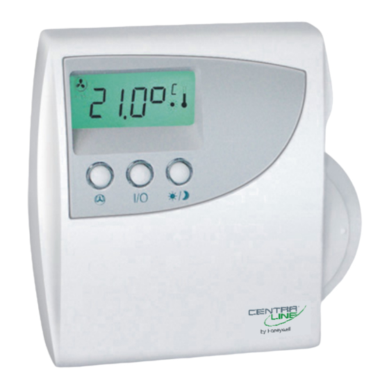
CLCM1H,6H,6T
Digital Wall Modules
FUNCTIONAL OVERVIEW
Table 1. Functional overview
model
sensor
CLCM1H112
temp. / humidity
CLCM6H212
temp. / humidity
CLCM6T21N
temperature
BEFORE INSTALLATION
All wiring must comply with local electrical codes and
ordinances or as specified on installation wiring diagrams.
Digital Wall Module (DWM) wiring can be sized from 1.5 to
2
0.34 mm
, depending on the application. The maximum
length of wire from a device to a DWM is 50 m. Twisted pair
wire is recommended for wire runs longer than 30.5 m.
CAUTION
EMI Noise Introduction. Risk of erratic system
operation.
Keep wiring at least 300 mm away from large induc-
tive loads such as motors, line starters, lighting
ballasts and large power distribution panels. During
installations, try to avoid areas of high EMI noise.
Run DWM wiring separately from 50 Vac or greater
power wiring.
WARNING / CAUTION
Risk of electric shock or equipment damage!
Do not touch any live parts inside the DWM housing.
►
Disconnect the power supply before making connections
►
to or removing connections from the DWM's terminals.
Do not reconnect the power supply until you have com-
►
pleted the installation.
If the DWM is powered via terminal 8 and connected to
►
earth ground, then the cable must be shielded.
Observe precautions for handling electrostatic sensitive
►
devices.
Copyright © 2014 Honeywell GmbH ● All Rights Reserved
Installation Instructions
suitable controllers
PANTHER
PANTHER
PANTHER + SERVAL
Cover Disassembly/Assembly
The DWM comes packed with a sub-base that mounts
separately for ease of installation; to disassemble the cover
and the sub-base, see Fig. 1. When re-attaching, make sure
that the latch on the underside of the DWM engages properly.
LIFT
2
1
PRESS
Fig. 1. Cover disassembly / assembly
INSTALLATION
NOTE:
Maintain a mounting clearance of approx. 10 cm on
both sides of the DWM in order to allow a free airflow
for the temperature sensor and accessibility of the
setpoint dial.
Do not mount the DWM on an outside wall, on a wall
containing water pipes, or near air ducts. Avoid
locations exposed to discharge air from registers or
radiation from lights, appliances, or the sun.
The wall modules can be mounted on a 60-mm wall outlet box
using 3.5-mm screws or on a wall (see Fig. 2). When
mounting directly on a wall, use the type of screws
appropriate for the wall material.
See Fig. 5 for bore-holes and mounting dimensions
(dimensions are the same for all models).
sub-base
cover
screw
Fig. 2. Mounting of DWM (CLCM6H,6T shown)
screw
MU1Z-0902GE51 R0214B
Werbung

Verwandte Anleitungen für Honeywell Centra Line CLCM1H112


Inhaltszusammenfassung für Honeywell Centra Line CLCM1H112
- Seite 1 If the DWM is powered via terminal 8 and connected to ► earth ground, then the cable must be shielded. Observe precautions for handling electrostatic sensitive ► devices. screw Fig. 2. Mounting of DWM (CLCM6H,6T shown) Copyright © 2014 Honeywell GmbH ● All Rights Reserved MU1Z-0902GE51 R0214B...
- Seite 2 CLCM1H,6H,6T DIGITAL WALL MODULES – INSTALLATION INSTRUCTIONS Wiring / Power Wiring with SERVAL (CLCM6T21N, only) Wiring with PANTHER triac NOTE: You should always first connect the DWM and only 8 9 10 11 12 0.5 A then install the PANTHER's software. 4 5 6 131415 1920 2122...
- Seite 3 CLCM1H,6H,6T DIGITAL WALL MODULES – INSTALLATION INSTRUCTIONS DIMENSIONS RESULT: The parameters with their currently set values are displayed; the ≡ behind the value indicates the currently set value (see below for values). 5. Release FAN OVERRIDE and turn the setpoint dial to select the parameter value.
- Seite 4 When the reset has been completed, the display will show Manufactured for and on behalf of the Environmental and Combustion Controls Division of Honeywell Technologies Sàrl, Rolle, Z.A. La Pièce 16, Switzerland by its Authorized Representative: CentraLine CentraLine Printed in Germany.
-
Seite 5: Funktionsübersicht
Erdungsanschluß vorhanden ist, muß das Kabel geschirmt sein. Schraube Elektrostatisch gefährdete Baugruppen (EGB) müssen mit ► Vorsicht behandelt werden. Abb. 2. Montage des DWM (abgebildet CLCM6H, 6T) Copyright © 2014 Honeywell GmbH ● Alle Rechte vorbehalten MU1Z-0902GE51 R0214B... - Seite 6 DIGITALE WANDMODULE CLCM1H, 6H, 6T – INSTALLATIONSANLEITUNG Verdrahtung, Stromversorgung Verdrahtung mit SERVAL (nur CLCM6T21N) Verdrahtung mit PANTHER triac HINWEIS: Die PANTHER-Software erst dann installieren, wenn 8 9 10 11 12 0.5 A das DWM angeschlossen ist. 4 5 6 131415 1920 2122 2324 2526...
- Seite 7 DIGITALE WANDMODULE CLCM1H, 6H, 6T – INSTALLATIONSANLEITUNG ABMESSUNGEN 4. FAN OVERRIDE gedrückt halten und gleichzeitig mit dem Einstellregler für den Sollwert die gewünschte Parameter-Nr. auswählen. ERGEBNIS: Die Parameter werden mit ihren aktuell ein- gestellten Werten angezeigt. Das Symbol ≡ hinter dem Wert markiert den aktuell eingestellten Wert (Werte siehe unten).
- Seite 8 Anschließend wird die aktuelle SW-version des DWM angezeigt (z. B. 2.11). Hergestellt für und im Auftrag des Geschäftsbereichs Environmental and Combustion Controls der Honeywell Technologies Sàrl, Rolle, Z.A. La Pièce 16, Schweiz in Vertretung durch: CentraLine In Deutschland gedruckt.
-
Seite 9: Avant L'installation
► terre, le câble doit être blindé. Respectez les précautions relatives à la manipulation des ► composants sensibles à l’électricité statique. Figuré 2. Montage du DWM (exemple du CLCM6H,6T) Copyright © 2014 Honeywell GmbH ● Tous droits réservés MU1Z-0902GE51 R0214B... - Seite 10 MODULES MURAUX NUMERIQUES CLCM1H,6H,6T – PROCEDURE D'INSTALLATION Câblage/Alimentation Câblage avec SERVAL (CLCM6T21N, uniquement) Câblage avec PANTHER triac REMARQUE: vous devez toujours d'abord brancher le DWM et 8 9 10 11 12 0.5 A ensuite seulement installer le logiciel PANTHER. 4 5 6 131415 1920 2122 2324...
- Seite 11 MODULES MURAUX NUMERIQUES CLCM1H,6H,6T – PROCEDURE D'INSTALLATION COTES RÉSULTAT: les paramètres s'affichent avec leurs valeurs actuelles. Le symbole ≡ après la valeur indique qu'il s'agit de la valeur actuellement définie (voir les valeurs ci-dessous). 5. Relâchez FAN OVERRIDE et tournez le cadran de point de consigne pour sélectionner la valeur des paramètres.
- Seite 12 -8 et +8 °F. Fabriqué pour et au nom de la division Environmental and Combustion Controls de Honeywell Technologies Sàrl, Rolle, Z.A. La Pièce 16, Suisse par son représentant autorisé: CentraLine Imprimé...
- Seite 13 Schroef Tref de nodige voorzorgsmaatregelen voor het werken met ► apparaten die gevoelig zijn voor statische elektriciteit. Afb. 2. Montage (CLCM6H, 6T weergegeven) Copyright © 2014 Honeywell GmbH ● Alle rechten voorbehouden MU1Z-0902GE51 R0214B...
- Seite 14 DIGITALE WANDMODULES CLCM1H, 6H, 6T– INSTALLATIE-INSTRUCTIES Bedrading/voeding Bedrading met de SERVAL (alleen CLCM6T21N) Bedrading met PANTHER triac OPMERKING: U moet altijd eerst de DWM aansluiten en dan pas de 8 9 10 11 12 0.5 A software van de PANTHER installeren. 4 5 6 131415 1920 2122...
- Seite 15 DIGITALE WANDMODULES CLCM1H, 6H, 6T – INSTALLATIE-INSTRUCTIES AFMETINGEN RESULTAAT: De parameters en de huidige waarden die voor de parameters zijn ingesteld, worden weer- gegeven; de ≡ achter de waarde geeft de momenteel ingestelde waarde aan (zie de waarden hieronder). 5. Laat de knop VENTILATOR OVERSCHRIJVEN los en draai aan het instelwiel voor de richtwaarde om de parameterwaarde te selecteren.
- Seite 16 8 tot en met +8 °F. versie van de DWM (bijvoorbeeld: 2.11) op het LCD-display wordt weergegeven. Honeywell Technologies Sàrl, Rolle, Z.A. La Pièce 16 Gefabriceerd voor en in opdracht van de Environmental and Combustion Controls Division van , Zwitserland door zijn daartoe gemachtigde vertegenwoordiging CentraLine Printed in Germany.