
Verwandte Anleitungen für Husqvarna SMR 511 2012 I.E.


Inhaltszusammenfassung für Husqvarna SMR 511 2012 I.E.
- Seite 1 SMR 511 2012 I.E. CARATTERISTICHE - USO - MANUTENZIONE IT - 1 Ed.00 - 12/2011 Dove non diversamente specificato, i dati e le prescrizioni si riferiscono a tutti i modelli.
-
Seite 2: Inhaltsverzeichnis
SOMMARIO Pag. Note l Le indicazioni di destra e sinistra si riferiscono ai due PRESENTAZIONE ............3 lati del motociclo rispetto al senso di marcia. AVVERTENZE IMPORTANTI..........3 DEFINIZIONE DI IMPIEGO ..........4 n° denti l Z: DATI PER L’IDENTIFICAZIONE ........5 DATI TECNICI ...............6 l A: Austria TABELLA DI LUBRIFICAZIONE, RIFORNIMENTI ....7 AUS:... -
Seite 3: Presentazione
1) I modelli SMR sono motocicli per impiego STRADALE ogni garanzia, in tutte le loro parti. La Vostra nuova motocicletta Husqvarna é stata pro- garantiti esenti da difetti e coperti da garanzia legale, a gettata e costruita per essere la migliore della sua condizione che VENGA MANTENUTA LA CONFIGURAZIONE categoria. -
Seite 4: Definizione Di Impiego
Sostituzione dei particolari zione eseguendo i tagliandi presso le ti condizioni: In caso di sostituzione dei particolari, usare unicamente par- officine autorizzate HUSQVARNA. - impiego prolungato a marcia prevalentemente costan- ticolari ORIGINALI Husqvarna. Il costo per la sostituzione dei pezzi e per la manodopera necessaria per ri- - impiego prolungato a pieno gas;... -
Seite 5: Dati Per L'identificazione
DATI PER L’IDENTIFICAZIONE Il numero di identificazione del motore è stampigliato sulla parte superiore del carter motore, mentre il numero di matricola del motociclo è stampigliato sul cannotto di sterzo del telaio. Riferite sempre, annotandolo anche sul presente libretto, il numero stampigliato sul telaio quando ordinate i ricambi o chiedete informazioni sul vostro motociclo. -
Seite 6: Dati Tecnici
DATI TECNICI TRASMISSIONE PRIMARIA SOSPENSIONE ANTERIORE Tipo forcella ....teleidraulica a steli Pignone motore ......Z 32 MOTORE Corona frizione . -
Seite 7: Tabella Di Lubrificazione, Rifornimenti
TABELLA DI LUBRIFICAZIONE, RIFORNIMENTI DIMENSIONI, PESO, CAPACITÀ Interasse ......mm 1460 Olio lubrificazione motore, cambio, trasmissione primaria . Lunghezza totale . -
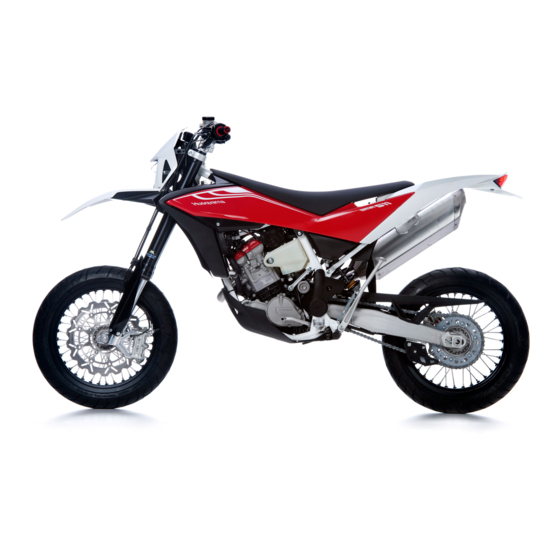
Seite 8: Vista Generale Moto
VISTA GENERALE MOTO CARATTERISTICHE - USO - MANUTENZIONE IT - 8... - Seite 9 LEGENDA 1. Ruota anteriore 2. Disco freno anteriore 3. Pinza freno anteriore 4. Forcella anteriore 5. Pedale comando cambio (si innesta la prima marcia spingendo in basso la leva; per tutte le altre marce spingerla in alto. La posizione di “folle” si trova tra la prima e la seconda marcia) 6.
-
Seite 10: Comandi
COMANDI ATTENZIONE*: Non riempire il serbatoio CARBURANTE oltre il limite inferiore del bocchettone Il carburante consigliato è benzina SENZA PIOMBO a 98 RUBINETTI CARBURANTE ottani. di carico. Dopo il rifornimento, accertarsi della corretta chiusura del tappo (2) del Nota*: Se il motore “batte in testa” uti- I due rubinetti (1) a vite posti sul lato sinistro dei serba- serbatoio. - Seite 11 CAVALLETTO LATERALE Controllare periodicamente il cavalletto laterale (vedi AVVIAMENTO A FREDDO Ogni motociclo è fornito di un cavalletto laterale (1). “Scheda di manutenzione periodica”); verificare che le molle non siano danneggiate e che il cavalletto si muova Questi modelli sono dotati di starter automatico sul corpo ATTENZIONE*: Il cavalletto è...
-
Seite 12: Strumento Digitale, Spie
3) di seguito saranno visualizzati alternativamente Concessionario HUSQVARNA. funzione impostata. “Km/h” e “Mph Miles”, premere nuovamente il pul- - Ad ogni spegnimento del motore, cessa la visualizza- sante SCROLL (A) nel momento che viene visualizzata zione delle funzioni dello strumento. - Seite 13 4- SPEED / CRONOMETRO (STP) 5- SPEED (figura 5) 2- SPEED / CLOCK (figura 2) (figura 4) - SPEED: velocità- Indicazione max: 299 Km/h o 299 - SPEED: velocità- Indicazione max: 299 Km/h o 299 mph; - SPEED: velocità- Indicazione max: 299 Km/h o 299 - CLOCK: orologio- Indicazione da 0:00 a 23:59:59.
- Seite 14 COMANDO GAS COMANDO FRENO ANTERIORE INTERRUTTORE DI ACCENSIONE La manopola (1) del gas è situata sul lato destro del La leva (2) del freno è situata sul lato destro del manu- manubrio. La posizione del comando sul manubrio può L’interruttore di accensione consta di due posizioni. brio.
-
Seite 15: Commutatore Destro Sul Manubrio
BLOCCASTERZO COMMUTATORE DESTRO SUL MANUBRIO COMMUTATORE SINISTRO SUL MANUBRIO Il commutatore destro ha i seguenti comandi: Il motociclo è fornito di un bloccasterzo (1) posto sul lato Il commutatore sinistro ha i seguenti comandi: destro del cannotto di sterzo. 1) Pulsante avviamento motore Sprazzo abbagliante (ritorno automatico) Per bloccare lo sterzo, operare nel modo seguente: 2) Interruttore di EMERGENZA arresto motore. -
Seite 16: Comando Frizione
COMANDO FRIZIONE COMANDO FRENO POSTERIORE La leva (1) di comando idraulico della frizione è situata Il pedale (1) di comando del freno posteriore si trova sul sul lato sinistro del manubrio ed è munita di protezione. lato destro del motociclo. La posizione del comando frizione sul manubrio può... -
Seite 17: Comando Cambio
ISTRUZIONI PER L’USO DEL MOTOCICLO COMANDO CAMBIO ISTRUZIONI PER IL RODAGGIO L’esclusività del progetto, l’elevata qualità dei materiali La leva (1) è posta sul lato sinistro del motore. Il pilota, NOTA*: Se non avete confidenza col impiegati e l’accuratezza del montaggio, Vi garantiscono ad ogni cambio di velocità, deve lasciare libero il pedale funzionamento del motociclo, prima di comfort sin dal primo momento. - Seite 18 INDIVIDUAZIONE DEGLI INCONVENIENTI DI FUNZIONA- Il motore é carente di potenza MENTO - Filtro aria sporco: pulire - Eccessiva distanza elettrodi candela: regolare Il seguente elenco di eventuali inconvenienti di funziona- - Gioco valvole non corretto: regolare mento serve, in linea generale, per individuarne l’origine - Compressione insufficiente: verificarne la causa ed attuarne il rimedio.
-
Seite 19: Avviamento Del Motore
AVVIAMENTO DEL MOTORE A motore freddo, cioè dopo prolungato fermo del mo- tociclo o in presenza di bassa temperatura ambienta- le, operare nel modo seguente: 1) Porre la chiave (1) dell’interruttore accensione in posizione ON (il ronzio che si avverte ruotando la chiave in posizione ON è... -
Seite 20: Arresto Del Motociclo E Del Motore
ARRESTO DEL MOTOCICLO E DEL MOTORE - Ruotare la chiave di avviamento (6) in posizione OFF (posizione di estrazione chiave) per spegnere - Chiudere completamente la manopola (1) del gas in il motore. modo da far decelerare il motociclo. - Frenare sia anteriormente (2) che posteriormente (3) mentre si scalano le marce (per una forte dece- lerazione, agire in modo deciso contemporaneamen- te sulla leva del freno anteriore e pedale del freno... - Seite 21 ARRESTO DEL MOTORE IN EMERGENZA CONTROLLO LIVELLO OLIO AVVERTENZA - Premere il pulsante rosso (7) per arrestare il moto- Il livello dellolio dipende dalla tempe- ratura dell’olio. quanto maggiore è la temperatura, tanto più alto è il livello dell’olio nella coppa dell’olio. Se si con- trolla il livello dell’olio a motore freddo o dopo tragitti brevi si può...
- Seite 22 AVVERTENZA SOSTITUZIONE OLIO MOTORE E PULIZIA- SOSTITUZIONE - svitare i due tappi (4) e rimuovere i due filtri a rete FILTRI METALLICI ED A CARTUCCIA (5) e (6); Accendere brevemente il motore per permettere all'olio di raggiungere tutti - controllare le condizioni degli anelli "OR" (7) , se usu- ATTENZIONE*: Fare attenzione a non toc- i punti del motore e controllare il livello rati sostituire, quindi effettuare la pulizia dei filtri (5)
-
Seite 23: Controllo Livello Liquido Di Raffreddamento
Nota *: CONTROLLO LIVELLO LIQUIDO DI RAFFREDDAMENTO SOSTITUZIONE LIQUIDO DI RAFFREDDAMENTO Potrebbero sorgere difficoltà nell’eliminare il liquido da ATTENZIONE*: L’operazione di sostitu- Controllare il livello (1) nel radiatore sinistro a motore superfici verniciate. Se così fosse, lavare con acqua. zione del liquido di raffreddamento freddo e con il motociclo in posizione verticale. - Seite 24 - Versare nel radiatore la quantità di liquido prescrit- ta e portare il motore in temperatura per eliminare eventuali bolle d’aria. - Attendere che il liquido di raffreddamento sia fred- do quindi, togliere il tappo (2) e controllare il livello come indicato nel paragrafo “Controllo livello liquido di raffreddamento”.
-
Seite 25: Regolazione Cavo Comando Gas
REGOLAZIONE CAVO COMANDO GAS - agire sulla vite di registro (8) fino ad ottenere un gio- co di 2 mm circa (0,08 in) in apertura; Per verificare la corretta registrazione della trasmissione - bloccare il controdado (5). di comando gas operare nel modo seguente: - rimontare il tutto procedendo in senso inverso. -
Seite 26: Registrazione Minimo
CONTROLLO CANDELA REGISTRAZIONE MINIMO La registrazione del minimo deve essere effettuata solo La distanza fra gli elettrodi della candela deve essere 0,7 a motore caldo e con comando gas in posizione chiusa ÷ 0,8 mm (0,028 ÷ 0,031 in). agendo nel modo seguente: Una distanza maggiore può... - Seite 27 AVVERTENZA*: Effettuare l’eventuale Per rimuovere la candela agire come segue: - rimuovere il coperchio filtro aria; sostituzione della candela, con una di - staccare il connettore (1) dal lato sinistro del motore; uguale gradazione, con estrema caute- - dal lato destro del motore con una chiave da 8 mm svitare la vite (2);...
-
Seite 28: Controllo Filtro Aria
CONTROLLO FILTRO ARIA - sganciare i fermi a levetta (4) e sfilare il filtro (5) dalla parte destra della moto, facendo attenzione ai - Ruotare in senso antiorario il perno (1) ed estrarre la due gancetti di ritegno; sella svincolandola dalla vite di fissaggio centrale; - rimuovere il fianchetto laterale destro (2) svitando con una chiave da 8 mm le cinque viti (3);... -
Seite 29: Pulizia Filtro Aria
- rimontare il tutto procedendo in senso inverso facen- REGOLAZIONE ANGOLO DI STERZATA - allargare le due linguette di fermo (6) e rimuovere il do attenzione a posizionare la spugna (8) del filtro telaietto (7) con la spugna (8); L'angolo di sterzata può essere variato agendo sui gruppi con la scitta "TOP"... - Seite 30 Concessionario sare irritazioni. Evitare il contatto con Il livello del fluido nel serbatoio della pompa non deve Husqvarna. la pelle e gli occhi. In caso di contatto, mai trovarsi al di sotto del valore minimo (3) indicato sul...
-
Seite 31: Registrazione Corsa A Vuoto Freno Posteriore
REGISTRAZIONE POSIZIONE PEDALE FRENO POSTERIORE REGISTRAZIONE CORSA A VUOTO FRENO POSTERIORE ATTENZIONE *: La mancanza della corsa a vuoto pre- La posizione del pedale di comando del freno posteriore Il pedale (3) di comando del freno posteriore, deve avere scritta provocherà la rapida usura delle rispetto all’appoggiapiede, può... - Seite 32 Concessio- nario Husqvarna. CARATTERISTICHE - USO - MANUTENZIONE IT - 32...
- Seite 33 SOSPENSIONI della molla per alzare la parte posteriore della moto. Le indicazioni che seguono costituiscono una guida indi- La sostituzione delle molle su entrambe le sospensioni è cativa per la messa a punto delle sospensioni in funzione consigliata per compensare l’aumento di peso della moto del tipo di terreno di impiego del motociclo.
-
Seite 34: Regolazione Forcella
REGOLAZIONE FORCELLA b) ESTENSIONE (REGISTRO SUPERIORE) c) SFIATO ARIA (da effettuare dopo ogni gara in caso di Taratura standard: -10 scatti (± 1 scatto) uso competitivo oppure mensilmente). a) COMPRESSIONE (REGISTRO INFERIORE) Porre il veicolo su un cavalletto centrale, estendere com- Taratura standard: -16 scatti (±... -
Seite 35: Registrazione Ammor Tizzatore
LIVELLO OLIO FORCELLA REGISTRAZIONE AMMOR TIZZATORE - Posizionare la moto a terra senza il pilota; Misurare la quota "A"; Per il regolare funzionamento della forcella é indispen- La taratura dell’ammortizzatore è definita per la marcia La differenza tra la quota "A" con ruota sollevata e sabile che in entrambe le gambe si trovi la prevista quan- con il solo pilota più... -
Seite 36: Registrazione Precarico Molla Ammortizzatore
REGISTRAZIONE PRECARICO MOLLA AMMORTIZZATORE - Pulire la controghiera (4) e la ghiera di registro (5) della molla (6). - Ruotare in senso antiorario il perno (1) ed estrarre la - Allentare la controghiera per mezzo di una chiave a sella svincolandola dalla vite di fissaggio centrale; gancio o con un punzone in alluminio. - Seite 37 REGISTRAZIONE FRENO IDRAULICO AMMORTIZZATORE alla posizione di tutto chiuso, quindi tornare indietro fino REGISTRAZIONE CATENA alle posizioni sopracitate. Per ottenere una frenatura più La catena deve essere controllata, registrata e lubrificata L’ammortizzatore è registrabile separatamente per la dolce, ruotare i registri in senso antiorario; agire inversa- in accordo con la “Tabella di manutenzione”;...
-
Seite 38: Lubrificazione Catena
Se così non risulta agire in questo modo: verso, facendo attenzione a posizionare correttamente LUBRIFICAZIONE CATENA - allentare sul lato destro, con chiave a bussola da 27 la molletta (1) e il giunto (2) e i relativi anelli OR. Lubrificare la catena attenendosi alle istruzioni che se- mm, il dado (2) di fissaggio del perno ruota;... - Seite 39 AVVERTENZA*: Controllare l’allinea- Lavaggio catena con anelli OR AVVERTENZA*: Il lubrificante per la ca- mento del guidacatena. Nel caso si fos- Lavare con petrolio, nafta o olio di paraffina; non usa- tena NON deve venire a contatto con il se piegato, potrebbe interferire con la pneumatico o il disco freno posteriori.
- Seite 40 Nota *: SMONTAGGIO RUOTA ANTERIORE Con la ruota smontata, non tirare la leva del freno per Posizionare un blocco o un cavalletto sotto il motore in non provocare l’avanzamento dei pistoncini della pinza. modo che la ruota anteriore sia sollevata dal terreno. Dopo la rimozione, appoggiare la ruota con il disco rivolto - Allentare le viti (1) che bloccano il perno ruota (2) sui verso l’alto.
- Seite 41 RIMONTAGGIO RUOTA ANTERIORE Nota *: Con la ruota smontata, non agire sul pedale del freno per - Montare il distanziale (D) sinistro sul mozzo ruota. non provocare l’avanzamento dei pistoncini della pinza. - inserire la ruota tra gli steli della forcella facendo in Dopo la rimozione, appoggiare la ruota con il disco ri- modo che il disco freno si inserisca nella pinza.
- Seite 42 FRENI PNEUMATICI I principali componenti dei due impianti sono: la pompa Abbiate cura di tenere i pneumatici gonfiati sempre alla freno con relativa leva (anteriormente) o pedale (poste- giusta pressione che deve corrispondere a quella indicata riormente), la tubazione, la pinza ed il disco. nella tabella “Dati Tecnici”...
- Seite 43 SMONTAGGIO PASTIGLIE FRENO ANTERIORE ANTERIORE - Montare le nuove pastiglie freno. POSTERIORE - Montare le mollette (3) spingendole verso il corpo pin- - Rimuovere le mollette (1). - Sfilare il perno (2). - Montare i perni (4) - Rimuovere le pastiglie. - Tirare verso l’esterno le mollette (3) controllando il corretto aggancio sui perni (4) ANTERIORE...
-
Seite 44: Ricarica Batteria
Antidoto: inconvenienti all’impianto elettrico, rivolgetevi al Conces- negativo NERO o BLU); ESTERNAMENTE: - Sciacquare con acqua. sionario HUSQVARNA. - estrarre la batteria (1) dal proprio alloggiamento. INTERNAMENTE: - Bevete grandi quantità Nel caso il veicolo debba rimanere inutilizzato per lunghi di latte o acqua. -
Seite 45: Sostituzione Lampadine Proiettore
SOSTITUZIONE LAMPADINE PROIETTORE Per accedere alle lampadine del proiettore, occorre pro- cedere nel modo seguente: - Svitare la vite superiore (1) utilizzando una chiave da 8 - svitare le due viti inferiori (2) utilizzando un cacciavite a stella; - spostare il gruppo faro (3); - sganciare il connettore (4);... - Seite 46 Per sostituire la lampada della luce di posizione (8) è SOSTITUZIONE LAMPADINE INDICATORI DI DIREZIONE FANALE POSTERIORE sufficiente sfilarla dalla calotta interna. Il fanale posteriore (1) è del tipo a LED; in caso di non - Svitare, con un cacciavite a stella, la vite (1); Effettuata la sostituzione, procedere al rimontaggio funzionamento deve essere sostituito.
- Seite 47 SOSTITUZIONE LAMPADA LUCE TARGA REGISTRAZIONE FANALE ANTERIORE L’eventuale rettifica dell’orientamento si può effettuare agendo come segue: - Svitare la vite (1) e staccare la luce targa (2) dal para- Per controllare se il fanale è orientato nel modo corretto fango; mettere il motociclo, con in pneumatici gonfiati alla giu- - Agire sulla vite (1) di regolazione;...
-
Seite 48: Appendice
APPENDICE - Versare olio fresco nel carter. - Controllare tutti i punti richiamati nella sezione “Con- INATTIVITA’ PROLUNGATA trolli e Registrazioni” (Appendice A). Dovendo lasciare inattivo il motociclo per un certo perio- - Lubrificare tutti i punti richiamati nella sezione “Lubri- do di tempo, effettuare la seguente preparazione: ficazione”... -
Seite 49: Operazioni Di Preconsegna
Freni / Frizione Controllo circuito � Serrature Controllo funzionalità � Comando acceleratore Controllo funzionalità � Serraggio viti e dadi Controllo / serraggio � 2a-senza tabelle-2004-OK 28-09-2004 16:42 Pagina 279 Comando acceleratore Verifica/regolazione gioco Fascette stringitubo Controllo / serraggio � � Comando starter Controllo funzionalità... -
Seite 50: Indice Alfabetico
INDICE ALFABETICO Pagina MONTAGGIO PASTIGLIE ..............43 USURA PASTIGLIE ................43 ARRESTO DEL MOTOCICLO E DEL MOTORE ........20 ARRESTO DEL MOTORE IN EMERGENZA ..........21 NOTA IMPORTANTE IN CASO DI AVVIAMENTO AVVIAMENTO DEL MOTORE ..............19 A FREDDO A BASSE TEMPERATURE ...........19 PNEUMATICI ...................42 BATTERIA ..................44 PULIZIA ..................48 BLOCCASTERZO ................15... - Seite 51 SMR 511 2012 I.E. SPECIFICATIONS - OPERATION - MAINTENANCE EN - 1 Ed.00 - 12/2011 Unless specified, data and prescription are referred to all the models.
- Seite 52 Note SUMMARY Page References to the “left” or “right” of the motorcycle are considered from the point of view of a person facing forward. PRESENTATION ............3 IMPORTANT NOTICES............3 number of teeth INTENDED USE .............4 l A: Austria IDENTIFICATION DATA ..........5 AUS: Australia TECHNICAL DATA ............6...
-
Seite 53: Presentation
1) SMR models are designed for ROAD use, guaran- are excluded from the warranty. Your new Husqvarna motorcycle is designed and man- teed free from faults, and covered by legal warranty ufactured to be the best in its field. The instructions in... -
Seite 54: Intended Use
Parts Replacement Nevertheless, it is not suitable for use under the follow- dicated in the user’s manual by carrying When parts replacement is required, use only Husqvarna out maintenance inspections at author- ing conditions: ORIGINAL parts. -
Seite 55: Identification Data
IDENTIFICATION DATA The engine identification number is stamped at the top of the crankcase, while vehicle serial number is stamped on the frame steering tube. Always quote the number stamped on the frame when ordering spare parts or requesting further details about your vehicle and note it on this booklet. -
Seite 56: Technical Data
TECHNICAL DATA CLUTCH REAR SUSPENSION Type ..oil bath multiple disc clutch, hydraulic control Type . .progressive with hydraulic single shock absorber ENGINE (preload regulation of spring and hydraulic brake in Type ....single cylinder, 4 stroke TRANSMISSION compression and extension) Liquid cooling with double radiator and electric fan. -
Seite 57: Table For Lubrication, Supplies
TABLE FOR LUBRICATION, SUPPLIES DIMENSION, WEIGHT, CAPACITY Wheelbase ......57.48 in Engine, gearbox and primary drive lubricating oil ..Overall length . -
Seite 58: Motorcycle Overall View
MOTORCYCLE OVERALL VIEW SPECIFICATIONS - OPERATION - MAINTENANCE EN - 8... - Seite 59 LEGEND 1. Front wheel 2. Front brake disc 3. Front brake calliper 4. Front fork 5. Gear shift pedal (the first gear is engaged by pushing lever downwards; for other gears push it upwards. The neutral gear is between the first and second gear) 6.
-
Seite 60: Controls
CONTROLS WARNING*: Do not overfill the tank. Re- FUEL fer to the lower mark on filler. After Recommended fuel: premium grade UNLEADED fuel FUEL TAPS (R.O.N. 98). refuelling, make sure the tank cap (2) is closed securely. Note*: If the engine "knocks", change The two screw taps (1) positioned on tanks left rear side, fuel brand or use a higher octane rat- shall always be left in fully OPEN position. - Seite 61 SIDE STAND Periodically check the side stand (see “Scheduled Main- COLD START A side stand (1) is supplied with every motorcycle. tenance Chart”); make sure that the springs are not dam- aged and the side stand freely moves. If the side stand is These models feature an automatic starter positioned WARNING*: The stand is designed to noisy, lubricate the fastening pivot (A).
- Seite 62 SW for the first 2 seconds; 3) the display will now alternate between “Km/h” and case, contact your HUSQVARNA dealer. after the check routine, the dashboard shows the last “Mph Miles”, push the SCROLL button (A) again while planned function.
- Seite 63 4- SPEED / LAP TIMER (STP) 5- SPEED (figure 5) 2- SPEED / CLOCK (figure 2) (figure 4) - SPEED: speed - maximum value: 299 Km/h or 299 mph - SPEED: speed - maximum value: 299 Km/h or 299 mph; - CLOCK: clock - reading from 0:00 to 23:59:59.
-
Seite 64: Throttle Control
THROTTLE CONTROL FRONT BRAKE CONTROL IGNITION SWITCH The throttle twistgrip (1) is located on the right-hand side The brake control lever (2) is located on the right-hand of the handlebar. The position of the throttle control can The ignition switch has two positions. side of the handlebar. -
Seite 65: Steering Lock
STEERING LOCK RIGHT-HAND HANDLEBAR SWITCH LEFT-HAND HANDLEBAR SWITCH The right-hand switch features the following controls: The motorcycle is equipped with a steering lock (1) on The left-hand handlebar switch contains the following the R.H. side of the steering head tube. commands: To lock it, proceed as follows: 1) Engine start button... -
Seite 66: Clutch Control
CLUTCH CONTROL REAR BRAKE CONTROL The hydraulic clutch control lever (1) is located on the left- The rear brake control (1) is placed on the right-hand hand side of the handlebar and is protected against dirt. side of the motorcycle. The position of the clutch control on handlebar can be adjusted by loosening the retaining screws (A). - Seite 67 INSTRUCTIONS FOR USING THE MOTORCYCLE GEAR SHIFT CONTROL INSTRUCTIONS FOR RUNNING-IN The exclusivity of the design, coupled to the high quality The lever (1) is placed on the left-hand side of the en- NOTE*: If you are not familiar with the of the materials used and the accuracy of the assembly, gine.
- Seite 68 TROUBLESHOOTING The engine knocks - excessive carbon deposit on the piston crown, or in the The following list is used for troubleshooting and to find combustion chamber: clean the necessary remedies. - faulty spark plug or wrong heat rating: replace The engine does not start The alternator fails to charge, or its charge is insufficient - the starting procedures are not correctly followed: fol-...
-
Seite 69: Engine Starting
ENGINE STARTING With cold engine, i.e., after the motorcycle has not been used for a while or in low ambient temperatures, operate in the following manner: 1) Turn key (1) in the ignition switch to ON (the hum you may hear when key is turned to ON is caused by the fuel pump pressurising the delivery system);... -
Seite 70: Stopping The Motorcycle And The Engine
STOPPING THE MOTORCYCLE AND THE ENGINE - Close the throttle (1) completely so that the engine will help slow down the motorcycle. - Apply both front (2) and rear (3) brakes while down- shifting (for fast deceleration, press firmly on the front brake lever and on the rear brake pedal at the same time). - Seite 71 ENGINE EMERGENCY STOP OIL LEVEL CHECK WARNING - Press the red button (7) to stop the engine. Oil level depends on oil temperature. The higher the temperature, the higher the oil level inside oil sump. Should oil level be checked with the engine cold or after short runs, wrong readings may be taken, with consequent wrong topping-up.
- Seite 72 WARNING ENGINE OIL REPLACEMENT AND MESH FILTERS-FILTER - loosen the two caps (4), and remove the two mesh CARTRIDGE CLEANING OR REPLACEMENT filters (5) and (6); Start the engine to allow the oil to reach all the points of the engine and check - check for O-rings (7) conditions.
-
Seite 73: Coolant Level Check
Note *: COOLANT LEVEL CHECK COOLANT REPLACEMENT Difficulties may arise in eliminating coolant from painted WARNING*: Coolant shall be replaced Check level (1) inside left radiator, with the engine cold surfaces. If this occurs, wash off with water. with cold engine and coolant. and the vehicle in vertical position. - Seite 74 - Pour the necessary quantity of coolant in the radiator then warm up the engine in order to eliminate any possible air bubbles. - Allow the coolant to cool down then remove cap (2) and check the level as explained under “Coolant level check”.
-
Seite 75: Throttle Control Cable Adjustment
WARNING*: Operation with damaged THROTTLE CONTROL CABLE ADJUSTMENT throttle control cable could result in an To check the correct adjustment of the throttle control unsafe riding condition. cable, operate as follows: - loosen screws (1) and remove protective cap (2); - turn throttle twistgrip (3) and make sure that there is a clearance of approx. -
Seite 76: Spark Plug Check
SPARK PLUG CHECK ADJUSTING THE IDLE Adjust the carburettor with warm engine and with the Spark plug electrodes gap shall be 0.7 - 0.8 mm (0.028 throttle control in closed position. Proceed as follows: ÷ 0.031 in). - turn adjuster screw (1) with a screwdriver until reach- A wider gap may cause difficulties in starting the engine ing an idle speed of 1,850 - 1,950 rpm, to be detected and overload the coil. - Seite 77 CAUTION*: Carefully change the spark To remove spark plug, proceed as follows: plug, if necessary, using one having the - remove the air filter cover; same rating. - disconnect connector (1) on engine left side; - on engine right side, undo screw (2) using an 8 mm wrench;...
- Seite 78 AIR FILTER CHECK - release retaining clips (4), and slide filter (5) out of vehicle right side, taking special care not to damage - Turn pin (1) counter clockwise and remove saddle the two retaining hooks; from central retaining screw; - remove right-hand side panel (2) by loosening the five screws (3) using an 8 mm wrench;...
-
Seite 79: Air Filter Cleaning
- refit all the disassembled parts in reverse order, mak- STEERING ANGLE ADJUSTMENT - widen the two retaining tabs (6) and remove sub- ing sure to position filter sponge (8) with the "TOP" frame (7) with sponge (8); To modify steering angle, turn the adjuster screws posi- wording facing up. - Seite 80 CAUTION*: Brake fluid may cause irrita- COUNTER CLOCKWISE “A”. checked by the Husqvarna Dealer. tion. Avoid contact with skin or eyes. In Fluid level inside master cylinder tank shall never be CAUTION*: Do not spill brake fluid onto case of contact, flush thoroughly with below the min.
- Seite 81 REAR BRAKE PEDAL POSITION ADJUSTMENT REAR BRAKE PEDAL FREE PLAY ADJUSTMENT WARNING*: When the free play requirement is not The position of the rear brake pedal with respect to the Before staring the braking action, rear brake pedal (3) met, the brake pads will be subjected footrest may be adjusted according to individual needs.
- Seite 82 Since it is dangerous to operate water and call a doctor if your eyes the motorcycle under such conditions, were exposed. have the brake system immediately checked by the Husqvarna Dealer. SPECIFICATIONS - OPERATION - MAINTENANCE EN - 32...
- Seite 83 SUSPENSION NOTES Hereinafter is a general guide for suspension adjustment, Should the fork be too soft or too hard under all adjust- based on the type of ground or use of the motorcycle. ment conditions, check oil level inside fork leg as it could Always start from the suspension standard setting before be too low or too high;...
- Seite 84 ADJUSTING THE FRONT FORK b) REBOUND (TOP ADJUSTER) c) BLEEDING (to carry out after each competition, or monthly). Standard setting: -10 clicks (± 1 click) Set the motorcycle on a central stand, release the fork a) COMPRESSION (LOWER ADJUSTER) fully extended and loosen the air vent valve (D). Once To reset standard calibration, turn adjuster (C) clockwise Standard setting: -16 clicks (±...
-
Seite 85: Oil Quantity In Each Fork Leg
740 cm (45.16 cu.in) WARNING*: Never disassemble the shock absorber, which contains compressed gas. Contact your Husqvarna Dealer for any major service. B: rear mudguard top height C: rear wheel axle height SPECIFICATIONS - OPERATION - MAINTENANCE... - Seite 86 ADJUSTING THE SHOCK ABSORBER SPRING PRELOAD - Clean spring (6) lock ring nut (4), and adjuster ring nut (5). - Turn pin (1) counter clockwise and remove saddle - Loosen lock ring nut using a hook wrench or an alu- from central retaining screw;...
- Seite 87 ADJUSTING THE SHOCK ABSORBER HYDRAULIC DAMPING Then turn them back to the above-mentioned positions. CHAIN ADJUSTMENT In order to obtain a smooth braking action, turn the ad- Chain should be checked, adjusted and lubricated as Adjustment of the compression stroke is independent justers counter clockwise.
-
Seite 88: Lubricating The Chain
If it is not, proceed as follows: Maintenance Chart. LUBRICATING THE CHAIN - on the right side, with a 27 mm Allen wrench, loosen - Check front and rear sprockets for damage. Lubricate the chain following these instructions. the locking nut (2) of the wheel axle; - Wash and lubricate chain as described in the relevant - loosen the check nuts (3) on both chain tensioners with paragraph. - Seite 89 CAUTION*: Check the chain guide align- Washing chain with O-rings CAUTION*: The chain lubricant shall NEV- ment, and remember that a bent element Wash using petroleum, naphtha or paraffin oil. Never ER get in contact with the tyres or the can cause chain early wear.
-
Seite 90: Removing The Front Wheel
Note *: REMOVING THE FRONT WHEEL Do not operate the front brake lever when the wheel has Set a stand or a block under the engine and see that the been removed; this causes the calliper pistons to move front wheel is lifted from the ground. outwards. -
Seite 91: Removing The Rear Wheel
REASSEMBLING THE FRONT WHEEL Note *: Do not operate the rear brake pedal when the wheel has - Fit wheel hub left spacer (D). been removed; this causes the calliper pistons to move - Insert wheel between fork legs, so as to couple brake outwards. - Seite 92 BRAKES TYRES The key components of the braking systems are: brake Care should be taken to keep the tyres properly inflated. master cylinder with its lever (front) or pedal (rear), See "Technical data" chart at the beginning of the manu- brake lines, calliper assembly and disc.
- Seite 93 BRAKE PADS REMOVAL - Install clips (3) by pushing them toward the calliper. FRONT - Install the pins (4). REAR - Pull clips (3) out, to make sure they are engaged on - Remove clips (1). pins (4) - Slide out pin (2). - Remove pads.
-
Seite 94: Battery Charger
When electrolyte leaks, or other failure of the electrical - remove the battery (1) from its housing. Antidote: system is detected, apply to the HUSQVARNA Dealer. EXTERNAL - Flush with water. If the vehicle remains unused for long periods, it is rec-... - Seite 95 HEADLAMP BULB REPLACEMENT Proceed as follows to reach the headlamp bulbs: - Loosen upper screw (1) using an 8 mm wrench; - loosen the two lower screws (2) using a Phillips screwdriver; - move headlight unit (3) aside; - release connector (4); - slide off the rubber gaiter (5);...
-
Seite 96: Tail Light
To replace the parking light bulb (8) extract it from the TURNING INDICATOR BULB REPLACEMENT TAIL LIGHT inside cover. - Loosen screw (1) using a Phillips screwdriver; The tail light (1) is a LED light; Replace it when it does - remove lens (2) and replace bulb (3) pushing it inside, Once the bulb has been replaced, reverse the above pro- not function. -
Seite 97: Headlight Adjustment
REPLACING THE NUMBER PLATE BULB HEADLIGHT ADJUSTMENT Beam height can be adjusted as follows: - loosen screw (1) and remove the number plate bulb When checking the proper aiming of the headlight beam: - Work adjuster screw (1); (2) from the mudguard; inflate tyres at the right pressure, have a person sit tighten to lower the beam, - take bulb holder (3) and bulb (4) out of the support;... -
Seite 98: Appendix
APPENDIX CLEANING LONG PERIOD OF INACTIVITY Before washing the motorcycle, it is necessary to: When the motorcycle is to be stored for a certain period, - remove the chassis lower caps (4); it should be prepared for storage as follows: - duly protect the following parts from water: - Clean the entire motorcycle thoroughly. -
Seite 99: Pre-Delivery Inspection
Interruttore accensione Controllo funzionalità Comando acceleratore Controllo funzionalità � Serraggio viti e dadi Controllo / serraggio � � Serrature Controllo funzionalità � Comando acceleratore Verifica/regolazione gioco Fascette stringitubo Controllo / serraggio � � Serraggio viti e dadi Controllo / serraggio �... - Seite 100 ALPHABETICAL INDEX GEAR SHIFT CONTROL ..............17 TAIL LIGHT ..................46 Page THROTTLE CONTROL ................14 THROTTLE CONTROL CABLE ADJUSTMENT .........25 ADJUSTING THE FRONT FORK ............34 HEADLAMP BULB REPLACEMENT ............45 TROUBLESHOOTING ................18 ADJUSTING THE IDLE...............26 HEADLIGHT ADJUSTMENT ..............47 Turning indicator BULB REPLACEMENT ..........46 ADJUSTING THE SHOCK ABSORBER ..........35 ADJUSTING THE SHOCK ABSORBER HYDRAULIC DAMPING ....37 TYRES.....................42...
- Seite 101 SMR 511 2012 I.E. CARACTERISTIQUES - UTILISATION - ENTRETIEN FR - 1 Ed.00 - 12/2011 Lorsque non différemment indiqué, les donneé et les instructions se réfèrent à tous les modèles.
- Seite 102 Remarques SOMMAIRE Page l Les indications « droite » et « gauche » se réfèrent aux deux côtés du motocycle par rapport au sens de PRÉSENTATION ............3 marche. AVERTISSEMENTS IMPORTANTS ........3 DÉFINITION D'EMPLOI ..........4 l Z : n° dents DONNÉES POUR L'IDENTIFICATION .......5 l A : Autriche DONNÉES TECHNIQUES ..........6...
-
Seite 103: Présentation
1) Les modèles SMR sont des motocycles à usage ROU- toute garantie, pour toutes les pièces. Votre nouvelle moto Husqvarna a été projetée et construi- TIER, garantis sans défauts et couverts par une garantie te pour être la meilleure dans son genre. Les instructions légale, à... -
Seite 104: Définition D'emploi
: En cas de remplacement de pièces, utiliser uniquement des ateliers autorisés HUSQVARNA. - utilisation prolongée à marche principalement constante ; pièces ORIGINALES Husqvarna. Le coût de remplacement des pièces et - utilisation prolongée à... -
Seite 105: Éléments D'identification
ÉLÉMENTS D’IDENTIFICATION Le numéro d’identification du moteur est gravé sur la partie supérieure du carter moteur, tandis que le numéro de matri- cule de la moto est gravé sur le tube de direction du châssis. Veuillez noter sur ce livret le numéro gravé sur le châssis, auquel vous devez vous référer lors d’une commande de pièces de rechange, ou lors d’une deman- de d’informations sur votre motocycle. -
Seite 106: Données Techniques
DONNÉES TECHNIQUES TRANSMISSION PRINCIPALE SUSPENSION AVANT Type fourche ... téléhydraulique inversée et Pignon moteur ......Z 32 MOTEUR Couronne embrayage . -
Seite 107: Tableau De Graissage, Ravitaillements
TABLEAU DE GRAISSAGE, RAVITAILLEMENTS DIMENSIONS, POIDS, CAPACITÉ Entraxe ......mm 1460 Huile de graissage du moteur, boîte de vitesses, transmission Longueur totale . -
Seite 108: Vue Générale De La Moto
VUE GÉNÉRALE DE LA MOTO CARACTERISTIQUES - UTILISATION - ENTRETIEN FR - 8... - Seite 109 LÉGENDE 1. Roue avant 2. Disque de frein avant 3. Étrier de frein avant 4. Fourche avant 5. Pédale sélecteur de vitesse (on enclenche la 1ère vitesse en poussant le levier vers le bas ; pour toutes les autres vitesses le pousser vers le haut.
-
Seite 110: Commandes
COMMANDES ATTENTION* : Ne jamais remplir le réser- CARBURANT voir au delà de la limite inférieure de la Carburant recommandé : essence SANS PLOMB 98. ROBINETS CARBURANT goulotte de remplissage. Assurez-vous Remarque* : Si le moteur « cogne », uti- que le bouchon (2) du réservoir soit liser une autre marque d’essence, ou un Les deux robinets (1) à... -
Seite 111: Béquille Latérale
BÉQUILLE LATÉRALE Contrôler la béquille latérale périodiquement (voir « Fi- DÉMARRAGE À FROID Chaque motocycle est doté d’une béquille latérale (1). che d’entretien périodique ») ; vérifier que les ressorts ne soient pas endommagés et que la béquille latérale Ces modèles sont dotés de starter automatique sur le ATTENTION* : La béquille a été projetée s'articule librement. - Seite 112 3) ensuite les symboles « Km/h » et « Mph Miles » sont dans ce cas s’adresser au concession- terminée la phase de contrôle, l’instrument visualise la visualisés alternativement ; appuyer à nouveau sur naire HUSQVARNA. dernière fonction réglée. le bouton SCROLL (A) quand est visualisée l'unité de - À chaque arrêt du moteur, l’afficheur cesse de visuali- mesure désirée.
- Seite 113 4- SPEED / CHRONOMÈTRE (STP) 5- SPEED (figure 5) 2- SPEED / CLOCK (figure 2) (figure 4) - SPEED : vitesse - Indication max : 299 Km/h ou 299 mph - SPEED : vitesse - Indication max : 299 Km/h ou 299 mph ; - CLOCK : horloge- Indication de 0:00 à...
-
Seite 114: Poignée Des Gaz
POIGNÉE DES GAZ COMMANDE FREIN AVANT COMMUTATEUR D'ALLUMAGE La poignée (1) des gaz est placée à droite du guidon. La La manette (2) de commande du frein avant est placée position de la commande sur le guidon peut être réglée Le commutateur d'allumage a deux positions. -
Seite 115: Antivol De Direction
ANTIVOL DE DIRECTION COMMUTATEUR DROIT SUR LE GUIDON COMMUTATEUR GAUCHE SUR LE GUIDON Le commutateur droit dispose des commandes suivantes : Le motocycle est équipé d'un antivol de direction (1) Le commutateur gauche dispose des commandes suivantes : placé au côté droit de la colonne de direction. flash d’avertissement (retour automatique) Pour bloquer la direction, procéder comme suit : 1) Bouton de démarrage moteur... -
Seite 116: Commande Frein Arrière
CommANde de L’emBrAyAGe COMMANDE FREIN ARRIÈRE Le levier (1) de commande hydraulique de l’embrayage est La pédale (1) de commande du frein arrière se trouve du situé à gauche sur le guidon et est muni d’une protection. côté droit de la moto. La position de la commande d'embrayage sur le guidon peut être réglée en desserrant les vis (A) de fixation. AVERTISSEMENT* Lors du freinage, un interrupteur d’arrêt allume le feu arrière. -
Seite 117: Instructions Pour L'utilisation Du Motocycle
INSTRUCTIONS POUR L’UTILISATION DE LA COMMANDE DE LA BOÎTE DE VITESSES INSTRUCTIONS DE RODAGE MOTO L’exclusivité du projet, la qualité élevée des matériaux Le levier (1) est placé sur le côté gauche du moteur. À cha- employés, ainsi que le montage soigné, vous garantis- que changement de vitesse, le conducteur doit libérer la pé- REMARQUE* : Si vous êtes peu familier sent le plus grand confort dès le premier instant. - Seite 118 LOCALISATION DES PROBLÈMES DE FONCTIONNEMENT - Jeu de soupapes incorrect : régler ; - Compression insuffisante : en vérifier la cause La liste suivante des éventuels problèmes de fonctionne- ment sert, en général, à en trouver l’origine et la solution. Le moteur cogne - Important dépôt de carbone sur la tête du piston ou Le moteur ne démarre pas dans la chambre de combustion : les nettoyer - Technique de démarrage inappropriée : suivre les ins-...
-
Seite 119: Démarrage Du Moteur
DÉMARRAGE DU MOTEUR Le moteur froid, à savoir après un arrêt prolongé de la moto ou si la température ambiante est basse, pro- céder comme suit : 1) Introduire la clé (1) dans le commutateur d'allumage en position ON (le vrombissement que l'on perçoit en tournant la clé... - Seite 120 ARRÊT DE LA MOTO ET DU MOTEUR - Tourner la clé de contact (6) sur OFF (position de retrait de la clé) pour arrêter le moteur. - Fermer complètement la poignée (1) de gaz de fa- çon à réduire la vitesse de la moto. - freiner aussi bien à l’avant (2) qu’à l’arrière (3) tout en rétrogradant (pour une forte décélération, appu- yer fermement sur le levier de frein avant et sur la...
- Seite 121 ARRÊT DU MOTEUR EN ÉTAT D'URGENCE CoNtrÔLe dU NiVeAU de L’HUiLe ATTENTION - Appuyer sur le bouton rouge (7) pour arrêter le mo- Le niveau de l'huile dépend de la tem- teur. pérature de l'huile ; plus la tempéra- ture est élevée, plus le niveau de l'huile est élevé...
- Seite 122 ATTENTION VidANGe d’HUiLe moteUr et NettoyAGe-remPLACe- - dévisser les deux bouchons (4) et déposer les deux MENT DES FILTRES MÉTALLIQUES ET À CARTOUCHE crépines de filtration (5) et (6) ; Mettre en marche le moteur pendant une courte période afin de permettre - contrôler l'état des joints toriques (7) et les remplacer ATTENTION* : Veillez à...
- Seite 123 Remarque * : CONTRÔLE DU NIVEAU DU LIQUIDE DE REFROIDISSEMENT SUBSTITUTION DU LIQUIDE DE REFROIDISSEMENT En cas de difficultés lors de l'élimination du liquide sur ATTENTION* : L’opération de vidange du Contrôler le niveau (1) dans le radiateur gauche, le moteur des surfaces vernies, laver à l’eau.
- Seite 124 - Verser la quantité de liquide nécessaire dans le radia- teur et chauffer le moteur pour éliminer d’éventuelles bulles d’air. - Attendre que le liquide de refroidissement refroidisse puis retirer le bouchon (2) et contrôler le niveau, com- me indiqué dans le paragraphe « Contrôle du niveau du liquide de refroidissement ». - Vérifier régulièrement les manchons d’assemblage (voir « fiche d’entretien périodique ») : cela prévien- dra des fuites du réfrigérant et par conséquent des...
-
Seite 125: Réglage Du Câble De Commande Des Gaz
RÉGLAGE DU CÂBLE DE COMMANDE DES GAZ - serrer le contre-écrou (5). - reposer le tout en suivant dans l'ordre inverse la mar- Pour vérifier le réglage de la transmission du câble de che de dépose. commande des gaz, procéder comme suit : - dévisser les vis (1) et déposer le cache (2) de protection ;... -
Seite 126: Réglage Du Ralenti
CoNtrÔLe de LA BoUGie d’ALLUmAGe RÉGLAGE DU RALENTI Régler le ralenti uniquement le moteur chaud, avec la La distance entre les électrodes de la bougie doit être 0,7 poignée des gaz en position fermée, et procéder de la ÷ 0,8 mm (0.028 ÷ 0.031 in). façon suivante : Une distance supérieure peut entraîner des difficultés de - à... - Seite 127 AVERTISSEMENT* : Remplacer éventuel- Pour déposer la bougie, agir comme suit : lement la bougie par une bougie de gra- - déposer le couvercle du filtre à air ; de identique avec extrême prudence. - débrancher le connecteur (1) du côté gauche du moteur ; - dévisser la vis (2) du côté droit du moteur à l'aide d'une clé...
-
Seite 128: Contrôle Du Filtre À Air
CONTRÔLE DU FILTRE À AIR - décrocher les butées à levier (4) et sortir le filtre (5) de la partie droite de la moto, en faisant attention - Tourner l'axe (1) dans le sens inverse des aiguilles aux deux agrafes de retenue ; d'une montre et sortir la selle en la dégageant de la vis de fixation centrale ;... - Seite 129 - reposer le tout en suivant dans l'ordre inverse la mar- RÉGLAGE DE L'ANGLE DE BRAQUAGE - écarter les deux languettes de butée (6) et déposer le che de dépose et en veillant à positionner la mousse sous-châssis (7) et la mousse (8) ; L'angle de braquage peut être changé...
- Seite 130 Concession- peut causer des irritations. Éviter tout Le niveau du fluide dans le réservoir du maître-cylindre naire Husqvarna. contact avec la peau et les yeux. Net- ne doit jamais être inférieur à la valeur minimale (3) AVERTISSEMENT* : Ne jamais verser le li- toyer la partie en contact et, s’il s’agit...
- Seite 131 RÉGLAGE DE LA POSITION PÉDALE DU FREIN ARRIÈRE RÉGLAGE DE LA COURSE À VIDE DU FREIN ARRIÈRE ATTENTION* : La pédale (3) de commande du frein arrière doit avoir L’absence de la course à vide prévue La position de la pédale de commande du frein arrière une course à...
- Seite 132 Étant donné qu’il des yeux, appeler un médecin. est dangereux de conduire le motocycle dans ces conditions, faire contrôler le système de freinage chez le Concession- naire Husqvarna. CARACTERISTIQUES - UTILISATION - ENTRETIEN FR - 32...
- Seite 133 SUSPENSIONS REMARQUES Les indications qui suivent constituent un guide indicatif Si la fourche est trop souple ou trop dure dans toutes les pour la mise au point des suspensions en fonction du conditions de réglage, vérifier le niveau de l'huile dans le type de terrain où...
-
Seite 134: Réglage De La Fourche
RÉGLAGE DE LA FOURCHE b) DÉTENTE (ÉLÉMENT DE RÉGLAGE SUPÉRIEUR) c) PURGE D'AIR (à effectuer après chaque compétition, Réglage standard : -10 déclics (± 1 déclic) autrement tous les mois). a) COMPRESSION ( ÉLÉMENT DE RÉGLAGE INFÉRIEUR) Placer la moto sur la béquille centrale, étendre complè- Réglage standard : -16 déclics (±... - Seite 135 740 cm (45,16 in portantes, contacter le Concessionnaire levée du sol. Husqvarna. B : Hauteur supérieure du garde-boue arrière C : axe de roue arrière CARACTERISTIQUES - UTILISATION - ENTRETIEN FR - 35...
- Seite 136 RÉGLAGE DE LA PRÉCHARGE DU RESSORT AMORTISSEUR - Nettoyer la contre-bague (4) et la bague de réglage (5) du ressort (6). - Tourner l'axe (1) dans le sens inverse des aiguilles - Desserrer la contre-bague à l'aide d'une clé à crochet d'une montre et sortir la selle en la dégageant de la ou d'un poinçon en aluminium.
-
Seite 137: Réglage De La Chaîne
RÉGLAGE DU FREIN HYDRAULIQUE AMORTISSEUR fermé soit atteinte, puis retourner en arrière jusqu'aux RÉGLAGE DE LA CHAÎNE positions susdites. Pour obtenir un freinage plus souple, La chaîne doit être contrôlée, réglée et lubrifiée confor- La course de compression peut être réglée séparément tourner les éléments de réglage dans le sens inverse des mément au «... - Seite 138 Dans le cas contraire, procéder de la façon suivante : - Vérifier que la chaîne n'est pas usée ou endommagée. LUBRIFICATION CHAÎNE - desserrer du côté droit, à l’aide d’une clé à douille de et la remplacer en suivant les instructions données Lubrifier la chaîne en suivant les instructions reportées 27 mm, l’écrou (2) de fixation de l'axe de roue ; dans le tableau d’entretien Périodique. Contrôler l'en- ci-dessous.
- Seite 139 AVERTISSEMENT* : Contrôler l’aligne- Lavage de la chaîne avec joints AVERTISSEMENT* : Le lubrifiant de la ment du rouleau de guide-chaîne. toriques chaîne NE DOIT JAMAIS entrer en contact Veillez à ce que ce rouleau ne soit pas avec le pneu ou le disque frein arrière. Laver au pétrole, mazout, ou huile de paraffine.
-
Seite 140: Dépose De La Roue Avant
Remarque * : DÉPOSE DE LA ROUE AVANT Lorsque la roue est démontée, ne pas tirer la poignée du Placer un chevalet ou un bloc sous le moteur de façon à frein, pour ne pas faire avancer les pistons de l’étrier. ce que la roue arrière soit soulevée du sol. -
Seite 141: Repose De La Roue Avant
REPOSE DE LA ROUE AVANT Remarque * : Lorsque la roue est démontée, ne pas baisser la pédale du - Monter l'entretoise (D) gauche sur le moyeu de roue. frein, pour ne pas faire avancer les pistons de l’étrier. - insérer la roue entre les tubes de fourche de façon à Après la dépose de la roue avant, poser la roue avec le ce que le disque de frein s'insère dans l'étrier. - Seite 142 FREIN PNEUS Éléments principaux des deux systèmes : maître-cylindre Vérifier avec soin que les pneumatiques soient toujours de frein avec levier (avant) ou pédale (arrière), tuyaute- gonflés à la bonne pression devant correspondre à la rie, étrier et disque. pression reportée dans le tableau des « Données techni- ques »...
- Seite 143 DÉPOSE DES PLAQUETTES DE FREIN AVANT AVANT - Monter les nouvelles plaquettes de frein. ARRIÈRE - Monter les clips (3) en les poussant vers le corps des - Enlever les agrafes (1). étriers. - Retirer le goujon (2). - Monter les goujons (4) - Enlever les plaquettes.
- Seite 144 ROUGE puis Antidote : électrique, s’adresser au Concessionnaire HUSQVArNA. le câble négatif NOIR ou BLEU) ; À L’EXTÉRIEUR : - Rincer à l’eau. Si la moto reste inutilisée pour de longues périodes, il est - sortir la batterie (1) de son compartiment.
- Seite 145 REMPLACEMENT DES AMPOULES DE PHARE Pour accéder à l’ampoule du phare, procéder comme suit : - Dévisser la vis supérieure (1) à l'aide d'une clé de 8 mm ; - dévisser les deux vis inférieures (2) à l'aide d'un tourne- vis étoile ; - déplacer l'ensemble phare (3) ; - débrancher le connecteur (4) ;...
-
Seite 146: Feu Arrière
Pour remplacer l’ampoule du feu de position (8) il suffit REMPLACEMENT DES AMPOULES CLIGNOTANTS FEU ARRIÈRE de la sortir de la calotte intérieure. - Dévisser la vis (1) à l'aide d'un tournevis étoile ; Le feu arrière (1) est de type à DEL ; en cas de dysfon- - déposer le transparent (2) et remplacer l'ampoule (3) en la Un fois le remplacement effectué, procéder à... - Seite 147 remPLACemeNt de L’AmPoULe d’ÉCLAirAGe de LA PLA- RÉGLAGE DU PHARE AVANT Le réglage éventuel de l'orientation est réalisé de la ma- QUe d’immAtriCULAtioN nière suivante : Pour contrôler l'orientation correcte du phare, placer la - Dévisser la vis (1) et retirer le feu de la plaque (2) du moto perpendiculaire à...
-
Seite 148: Annexe
ANNEXE - Contrôler tous les points indiqués dans la section « Con- trôles et Réglages » (Annexe A). LoNGUeS PÉriodeS d’iNACtiVitÉ - Lubrifier tous les points indiqués dans la section « Lu- Après une longue période d’inactivité, préparer le moto- brification » (Annexe A). cycle comme suit : - Nettoyage général du motocycle. NETTOYAGE - Vidanger le carburant du réservoir. -
Seite 149: Opérations De Prélivraison
Freni / Frizione Controllo circuito � Serrature Controllo funzionalità � Comando acceleratore Controllo funzionalità Serraggio viti e dadi Controllo / serraggio � � 2a-senza tabelle-2004-OK 28-09-2004 16:42 Pagina 280 Comando acceleratore Verifica/regolazione gioco � Fascette stringitubo Controllo / serraggio � Comando starter Controllo funzionalità... -
Seite 150: Index Alphabétique
INDEX ALPHABÉTIQUE Page LOCALISATION DES PROBLÈMES DE FONCTIONNEMENT .....18 SUBSTITUTION DU LIQUIDE DE REFROIDISSEMENT ......23 LoNGUeS PÉriodeS d’iNACtiVitÉ ...........48 SUSPENSIONS ................33 AFFICHEUR NUMÉRIQUE, VOYANTS ..........12 LUBRIFICATION CHAÎNE ..............38 ANTIVOL DE DIRECTION ..............15 ARRÊT DE LA MOTO ET DU MOTEUR ..........20 USURE DES PLAQUETTES ..............43 ARRÊT DU MOTEUR EN ÉTAT D'URGENCE ..........21 MONTAGE DES PLAQUETTES ............43 VidANGe d’HUiLe moteUr et NettoyAGe-remPLACemeNt deS fiLtreS... - Seite 151 SMR 511 2012 I.E. MERKMALE - GEBRAUCH - WARTUNG DE - 1 Ed.00 - 12/2011 Wo nicht anders ausdrücklich angegeben, beziehen sich die Daten und die Vorschriften auf alle Modelle.
- Seite 152 Anmerkungen INHALTSVERZEICHNIS Seite. Die Angaben rechts und links beziehen sich auf die beiden Seiten des Motorrads in Bezug auf die Fahrtrichtung. EINFÜHRUNG...............3 WICHTIGE HINWEISE ............3 Anzahl Zähne DEFINITION DES EINSATZES ..........4 l A: Österreich RAHMEN UND MOTORNUMMER ........5 AUS: Australien Belgien TECHNISCHE ANGABEN ..........6 Brasilien...
-
Seite 153: Einführung
Willkommen in der Familie der Husqvarna-Motorradfahrer! 1) Die Modelle SMR sind Motorräder für den Ein- Teilen von allen Garantieleistungen Ihr neues Husqvarna-Motorrad ist entworfen und herge- satz auf der STRASSE, die garantiert keinerlei Mängel stellt worden, um das beste aus seiner Klasse zu sein. -
Seite 154: Anmerkung
- längerer Einsatz bei Höchstgeschwindigkeit; Bei einem Wechseln von Bauteilen ausschließlich ORIGINAL- - Einsatz mit Gepäck; Bauteile Husqvarna benutzen. ACHTUNG*: ACHTUNG* Beim Fahren von mehr als Bitte STETS beachten, dass die Motor- ACHTUNG*: Nach einen Sturz muss das Motor- zwei aufeinanderfolgenden Minuten räder, die an jeglicher Art von Wett-... -
Seite 155: Rahmen Und Motornummer
RAHMEN UND MOTORNUMMER Die Motor-Identifizierungsnummer ist im oberen Teil des Motorgehäuses eingeprägt, während die Rahmne- nummer des Motorrads auf dem Lenkrohr des Rahmens eingeprägt ist. Die Rahmennummer sollte in die vorliegende Bedie- nungs- und Wartungsanleitung eingetragen werden. Die Rahmennummer muss bei Ersatzteilbestellungen oder bei Anfragen nach Informationen immer angege- ben werden. -
Seite 156: Technische Angaben
TECHNISCHE ANGABEN HAUPTANTRIEB VORDERE RADAUFHÄNGUNG/FEDERUNG Hydraulische ..Upside-Down-Teleskopgabel und Antriebsritzel......Z 32 MOTOR vorgerückte Achse (einstellbar hinsichtlich Druckstufe Zahnkranz Kupplung . -
Seite 157: Tabelle Schmiermittel, Betriebsflüssigkeiten
TABELLE SCHMIERMITTEL, BETRIEBSFLÜSSIG- (%) - Nur Fahrer (&) - Fahrer und Beifahrer KEITEN Schmieröl Motor, Getriebe, Hauptantrieb ... . . ABMESSUNGEN, GEWICHT, FÜLLMENGEN ......CASTROL GPS SAE 10W-40 Motor-Kühlflüssigkeit . -
Seite 158: Allgemeine Ansicht Des Motorrads
ALLGEMEINE ANSICHT DES MOTORRADS MERKMALE - GEBRAUCH - WARTUNG DE - 8... -
Seite 159: Zeichenerklärung
ZEICHENERKLÄRUNG 1. Vorderrad 2. Bremsscheibe Vorderradbremse 3. Bremssattel Vorderradbremse 4. Vordere Gabel 5. Schaltpedal (der erste Gang wird eingelegt durch Drücken des Hebels nach unten; für alle anderen Gänge muss das Pedal nach oben ge- drückt werden. Die "Leerlauf"-Position befindet sich zwischen dem 1. -
Seite 160: Schalter Und Bedienelemente
SCHALTER UND BEDIENELEMENTE ACHTUNG*: Den Tank nicht über den un- KRAFTSTOFF teren Rand des Einfüllstutzens füllen. Der empfohlene Kraftstoff ist BLEIFREIES Benzin mit 98 Oktan. BENZINHÄHNE Nach dem Tanken kontrollieren, dass der Anmerkung*: Wenn der Motor "klopft", Tankdeckel (2) richtig geschlossen ist. eine andere Benzinmarke oder einen Die beiden Schraubhähne (1) auf der linken Seite der Kraftstoff mit höherer Oktanzahl ver-... -
Seite 161: Achtung*: Das Fahrzeug Darf Erst
SEITENSTÄNDER Den Seitenständer regelmäßig kontrollieren (siehe KALTSTART Jedes Fahrzeug ist mit einem Seitenständer (1) ausge- "Wartungsplan”). Prüfen, dass die Federn nicht beschä- stattet. digt sind, und dass sich der Seitenständer frei bewegt. Diese Modelle sind mit einer Start-Automatik am Drossel- Ist der Seitenständer laut, den Befestigungsbolzen (A) körper versehen, die sich automatisch entsprechend der ACHTUNG*: Der Seitenständer ist so... -
Seite 162: Wichtig: Bei Störungen An Der Einspritzanlage
- Jedes Mal, wenn die Batterie angeschlossen wird, wird 3) Anschließend werden abwechselnd “km/h” und “Mph sem Fall an einen HUSQVARNA Vertrags- während der ersten 2 Sekunden die Version der Steuer- Miles” angezeigt. In dem Moment, in dem die Einheit händler. - Seite 163 4- SPEED / CHRONOMETER (STP) 5- SPEED (Abbildung 5) 2- SPEED / CLOCK (Abbildung 2) (Abbildung 4) - SPEED: Geschwindigkeit – Max. Anzeige: 299 km/h o - SPEED: Geschwindigkeit – Max. Anzeige: 299 km/h 299 mph oder 299 mph; - SPEED: Geschwindigkeit – Max. Anzeige: 299 km/h - CLOCK: Uhrzeit - Anzeige von 0:00 bis 23:59:59.
-
Seite 164: Zündschloss
GASGRIFF BREMSHEBEL VORDERRADBREMSE ZÜNDSCHLOSS Der Gasgriff (1) befindet sich rechts am Lenker. Durch Lö- Der Bremshebel (2) befindet sich rechts am Lenker. Durch sen der beiden Befestigungsschrauben kann die Position Das Zündschloss hat zwei Positionen. Lösen der beiden Befestigungsschrauben kann die Position des Bremshebels am Lenker eingestellt werden. -
Seite 165: Schalter Rechts Am Lenker
LENKERSCHLOSS SCHALTER RECHTS AM LENKER LINKER SCHALTER AM LENKER Der rechte Schalter hat folgende Steuerungen: Das Motorrad ist mit einem Lenkerschloss (1) ausgestattet, Der linke Schalter hat folgende Steuerungen: das sich auf der rechten Seite des Lenkrohrs befindet. Lichthupe (stellt sich automatisch zurück) Zum Blockieren des Lenkers wie folgt vorgehen: 1) Motoranlasserknopf Den Lenker nach links drehen, den Schlüssel in das... - Seite 166 KUPPLUNGSHEBEL BREMSPEDAL HINTERRADBREMSE Der Kupplungshebel (1) für die hydraulische Betätigung Das Bremspedal (1) für die Hinterradbremse befindet der Kupplung befindet sich links am Lenker und ist mit sich auf der rechten Seite des Motorrads. einem Schutzschalter ausgestattet. Durch Lösen der beiden Befestigungsschrauben (A) kann die Position des Kupplungshebels am Lenker eingestellt Über einen Bremslichtschalter wird das Bremslicht beim werden (A).
-
Seite 167: Bedienungsanleitung Für Das Motorrad
beim Runterschalten in den nächstklei- SCHALTPEDAL ANLEITUNGEN FÜR DAS EINFAHREN neren Gang „übertourig“ laufen und Der exklusive Entwurf, die hohe Qualität der verwende- Das Schaltpedal (1) befindet sich links am Motor. Der die Straßenhaftung des Hinterrads ver- ten Materialien und die sorgfältige Montage garantieren Fahrer muss nach jedem Schaltvorgang das Pedal loslas- loren gehen würde. -
Seite 168: Feststellen Von Betriebsstörungen
FESTSTELLEN VON BETRIEBSSTÖRUNGEN - Falsches Ventilspiel: Einstellen. - Unzureichende Verdichtung: Die Ursache suchen. Die folgende Liste eventueller Betriebsstörungen dient all- gemein zur Feststellung der Ursachen und zur Abhilfe. Der Motor klopft - Starke Kohleablagerung am Kolbenboden oder im Der Motor startet nicht Brennraum: Reinigen. -
Seite 169: Starten Des Motors
STARTEN DES MOTORS Bei kaltem Motor, d. h. nach längerem Stillstand des Motorrads oder bei niedrigen Temperaturen, wie folgt vorgehen: 1) Den Schlüssel (1) des Zündschlosses in die Stellung ON bringen (das Summen, das beim Drehen des Schlüssels in die Position ON wahrzunehmen ist, entsteht aufgrund der Kraftstoffpumpe, welche die Versorgungsanlage unter Druck bringt);... -
Seite 170: Anhalten Des Motorrads Und Abstellen Des Motors
ANHALTEN DES MOTORRADS UND ABSTELLEN DES MOTORS - Den Startschlüssel (6) in die OFF-Stellung bringen (die Stellung zum Herausziehen des Schlüssels), um - Den Gasgriff (1) vollständig schließen, so dass das den Motor auszuschalten. Motorrad Geschwindigkeit verliert. - Sowohl mit der Vorderradbremse (2) als auch mit der Hinterradbremse (3) bremsen und gleichzeitig die Gän- ge runterschalten (Für eine starke Verzögerung gleich- zeitig und kräftig den Bremshebel der Vorderradbremse... -
Seite 171: Kontrolle Motorölstand
ABSTELLEN DES MOTORS IM NOTFALL KONTROLLE MOTORÖLSTAND HINWEIS - Den roten Taster betätigen (7), um den Motor zum Der Ölstand hängt von der Öltempera- Stillstand zu bringen. tur ab. Je höher die Temperatur, desto höher der Ölstand im Ölbehälter. Wird der Ölstand bei kaltem Motor kontrolliert oder nach kurzen Fahrten, so können falsche Auslegungen die Folge sein und... - Seite 172 MOTORÖLWECHSEL UND REINIGUNG – WECHSELN DER - die beiden Deckel (4) abschrauben und die beiden - nach dem Wechseln des Filters die Öl-Ablassschraube METALLFILTER UND FILTERPATRONE Filtergitter (5) und (6) entfernen; (3) wieder anbringen und die vorgesehene Menge Öl - den Zustand der Ringe "OR" (7) kontrollieren und, einfüllen.
-
Seite 173: Kontrolle Kühlflüssigkeitsstand
Anmerkung *: KONTROLLE KÜHLFLÜSSIGKEITSSTAND WECHSELN DER KÜHLFLÜSSIGKEIT Es könnte schwierig sein die Flüssigkeit von lackierten Den Stand (1) im linken Kühler bei kaltem Motor und ACHTUNG*: Zum Wechseln der Kühlflüs- Oberflächen zu beseitigen. In diesem Fall muss mit Was- dem Motorrad in vertikaler Stellung kontrollieren. Die sigkeit müssen der Motor und die Flüs- ser abgespült werden. - Seite 174 - Die angegebene Flüssigkeitsmenge in den Kühler einfüllen und den Motor auf Betriebstemperatur brin- gen, um eventuelle Luftbläschen zu beseitigen. - Abwarten, dass sich die Kühlflüssigkeit abkühlt, den Deckel (2) abnehmen und den Füllstand wie im Ab- satz "Kontrolle Kühlflüssigkeitsstand" beschrieben kontrollieren. - Die Anschlussmuffen regelmäßig kontrollieren (sie- he "Wartungsplan").
-
Seite 175: Einstellung Des Gaszugs
EINSTELLUNG DES GASZUGS - auf die Einstellschraube (8) einwirken, bis ein Spiel von etwa 2 mm (0.08 in) in geöffneter Stellung er- Für die Kontrolle der richtigen Einstellung des Gaszugs reicht ist; wie folgt vorgehen: - die Kontermutter (5) blockieren; - die Schrauben lösen (1) und den Schutzdeckel (2) - Beim Wiedereinbau in umgekehrter Reihenfolge wie entfernen;... -
Seite 176: Leerlaufeinstellung
KONTROLLE ZÜNDKERZE LEERLAUFEINSTELLUNG Die Leerlaufeinstellung darf nur bei warmem Motor und Der Abstand zwischen den Elektroden der Zündkerze geschlossenem Gasgriff vorgenommen werden. Wie folgt muss 0,7 ÷ 0,8 mm (0.028 ÷ 0.031 in) betragen. vorgehen: Ein größerer Abstand kann Startschwierigkeiten und eine - mit einem Schraubendreher auf die Einstellschraube Überlastung der Zündspule verursachen. - Seite 177 HINWEIS*: Bei einem Kerzenwechsel Zum Entfernen der Zündkerze wie folgt vorgehen: - den Deckel des Luftfilters entfernen; sehr vorsichtig vorgehen und die Zünd- - den Kabelstecker (1) von der linken Seite des Motors lösen; kerze mit einer Kerze mit gleichem ther- - von der rechten Seite des Motors mit einem 8 mm- mischen Wirkungsgrad ersetzen.
- Seite 178 KONTROLLE LUFTFILTER - die Hebelverschlüsse lösen (4) und den Filter (5) aus dem rechten Teil des Motorrads entnehmen, hierbei - Entgegen dem Uhrzeigersinn den Stift (1) drehen und auf die beiden Rückhaltehäkchen achten; die Sitzbank durch Herauslösen aus der zentralen Be- festigungsschraube entnehmen;...
-
Seite 179: Reinigung Luftfilter
tausch erforderlich ist; EINSTELLUNG LENKEINSCHLAG - die beiden Feststelllaschen öffnen (6) und den Rah- - alles wieder in umgekehrter Reihenfolge einbauen men (7) mit dem Filterschwamm (8) entfernen; Der Lenkeinschlag kann durch Einwirken an den Stell- und dabei darauf achten, dass der Filterschwamm schrauben an den Seiten des Lenkrohrs in der folgenden (8) mit der Aufschrift "TOP"... - Seite 180 Positionen eingestellt werden. Um den Hebel (1) an zu fahren, muss die Bremsanlage sofort vorhandene Bremsflüssigkeit vollstän- den Griff anzunähern, die Stellvorrichtung (2) GEGEN DEN bei einem Husqvarna-Vertragshändler dig beseitigt werden. UHRZEIGERSINN "A" drehen. kontrolliert werden. Der Flüssigkeitsstand im Behälter am Hauptbremszylin- HINWEIS*: Keine Bremsflüssigkeit auf...
-
Seite 181: Einstellung Pedalposition Hinterradbremse
EINSTELLUNG PEDALPOSITION HINTERRADBREMSE EINSTELLUNG DES LEERHUBS HINTERRAD-BREMSPEDAL ACHTUNG *: Fehlt der vorgeschriebene Leerhub, Die Position des Hinterrad-Bremspedals in Bezug auf die Das Hinterrad-Bremspedal (3) muss einen Leerhub (B) führt dies zu einem vorzeitigen Ver- Fußraste kann je nach persönlichen Bedürfnisse einge- von 5 mm (0.196 in) aufweisen, bevor der Bremsvor- schleiß... - Seite 182 Motorrad unter diesen Bedingungen takt mit Haut und Augen unbedingt zu fahren, muss die Bremsanlage sofort vermeiden. Bei einem Kontakt den be- bei einem Husqvarna-Vertragshändler troffenen Bereich vollständig reinigen. kontrolliert werden. Sind die Augen betroffen, muss ein Arzt aufgesucht werden.
-
Seite 183: Radaufhängung/ Federung
RADAUFHÄNGUNG/ FEDERUNG beiden Aufhängungen wird angeraten, um das gesteiger- Die nachfolgenden Angaben sind eine Richtschnur für die te Gewicht des Motorrads aufgrund des angesammelten Einstellung der Aufhängungen entsprechend der Art des Schlamms auszugleichen. Untergrunds, auf dem das Motorrad zum Einsatz kommt. Vor jeder Änderung, aber auch anschließend, falls die ANMERKUNGEN neue Einstellung nicht zufriedenstellend ist, muss immer... -
Seite 184: Zugstufe ( Obere Stellvorrichtung)
EINSTELLUNG GABEL b) ZUGSTUFE ( OBERE STELLVORRICHTUNG) c) ENTLÜFTEN (nach jedem Rennen ausführen, falls die Standard-Einstellung: -10 Rasten (± 1 Rasten) Maschine bei Rennen eingesetzt wird, oder ansonsten a) DRUCKSTUFE (UNTERE STELLSCHRAUBE) monatlich). Soll wieder auf die Standard-Einstellung zurückgestellt Standard-Einstellung: -16 Rasten (± 1 Rasten) Das Fahrzeug auf den Hauptständer stellen, die Gabel werden, die Stellvorrichtung (C) in Uhrzeigersinn bis auf Soll wieder auf die Standard-Einstellung zurückgestellt... -
Seite 185: Ölmenge In Jedem Schaft
ACHTUNG*: Den Stoßdämpfer niemals Hinterrad zu bestimmen. zerlegen, das er unter Druck stehendes Gas enthält. Für größere Arbeiten wen- B: Obere Höhe hinterer Kotflügel den Sie sich bitte an einen Husqvarna- C: Hinterradachse Vertragshändler. MERKMALE - GEBRAUCH - WARTUNG DE - 35... -
Seite 186: Einstellung Federvorspannung Stossdämpfer
EINSTELLUNG FEDERVORSPANNUNG STOSSDÄMPFER - Den Gegengewindering (4) und den Einstell-Gewinde- ring (5) der Feder (6) reinigen. - Entgegen dem Uhrzeigersinn den Stift (1) drehen und - Den Gegengewindering mittels eines Nutenschlüssels die Sitzbank durch Herauslösen aus der zentralen Be- mit einem Aluminiumstempel lösen. festigungsschraube entnehmen;... -
Seite 187: Einstellung Hydraulische Dämpfung Stossdämpfer
EINSTELLUNG HYDRAULISCHE DÄMPFUNG STOSSDÄMPFER Positionen zurückstellen. Um eine weichere Dämpfung EINSTELLUNG KETTE zu erhalten, die Stellvorrichtung gegen den Uhrzeiger- Die Kette muss entsprechend der Angaben aus dem "War- Der Stoßdämpfer kann getrennt für das Durchfedern in sinn drehen. Um eine härtere Dämpfung zu erhalten, die tungsplan"... -
Seite 188: Schmieren Der Kette
Andernfalls wie folgt vorgehen: chenden Ringe OR korrekt positioniert sind. SCHMIEREN DER KETTE - Auf der rechten Seite mit einem 27 mm Steckschlüssel - Kontrollieren, dass die Kette nicht abgenutzt oder Beim Schmieren der Kette die folgenden Anleitungen die Radachsmutter (2) lösen. beschädigt ist. - Seite 189 HINWEIS*: Die Ausrichtung der Ketten- Waschen der Kette mit Ringen OR HINWEIS*: Das Ketten-Schmiermittel darf führung überprüfen. Ist sie verbogen, Mit Erdöl, Dieselkraftstoff oder Paraffinöl waschen. Um NICHT mit den Reifen oder der hinteren kann sie an der Kette schleifen und Bremsscheibe in Berührung kommen.
-
Seite 190: Ausbau Des Vorderrads
Anmerkung *: AUSBAU DES VORDERRADS Bei ausgebauten Rad niemals den Bremshebel betätigen, Einen Block oder einen Ständer unter den Motor stellen, damit die Bremskolben am Bremssattel nicht austreten. so dass das Vorderrad vom Boden angehoben ist. Nach dem Ausbau das Rad so ablegen, dass die Brems- - Die Schrauben lösen (1), die die Radachse (2) auf scheibe nach oben weist. -
Seite 191: Wiedereinbau Vorderrad
WIEDEREINBAU VORDERRAD Anmerkung *: Bei ausgebauten Rad niemals das Bremspedal betätigen, - Den linken Abstandhalter (D) auf die Radnabe montieren. damit die Bremskolben am Bremssattel nicht austreten. - Das Rad zwischen die Schäfte der Gabel einführen, sodass Nach dem Ausbau das Rad so ablegen, dass die Brems- sich die Bremsscheibe in den Bremssattel positioniert. - Seite 192 BREMSEN REIFEN Die wichtigsten Bauteile der beiden Anlagen sind: Der Darauf achten, dass die Reifen immer den richtigen Reifen- Hauptbremszylinder mit dem entsprechenden Brems- druck haben. Der Reifendruck muss den Angaben aus der hebel (Vorderradbremse) oder Bremspedal (Hinterrad- Tabelle "Technische Angaben" entsprechen, die sich am bremse), die Bremsleitungen, der Bremssattel und die Anfang der Bedienungs- und Wartungsanleitung befindet.
- Seite 193 AUSBAU BREMSBELÄGE VORNE VORNE - Die neuen Bremsbeläge einbauen. HINTEN - Die Federn (3) zum Einbau in Richtung Bremssattelge- - Die Federn (1) entfernen. häuse drücken. - Den Stift (2) herausziehen. - Die Stifte (4) einbauen. - Die Bremsbeläge ausbauen. - Die Federn (3) nach außen ziehen und kontrollieren, ob sie richtig in die Stifte (4) eingehakt sind.
-
Seite 194: Batterieladung
Anlage auftreten, wenden Sie sich bitte dereinbau zuerst das ROTE Pluskabel und dann das ÄUSSERLICH: - Mit Wasser abspülen. an einen HUSQVARNA-Vertragshändler. SCHWARZE oder BLAUE Minuskabel anschließen). INNERLICH: - Viel Milch oder Wasser trin- Sollte das Fahrzeug für längere Zeit nicht genutzt wer- - Die Batterie (1) aus ihrem Sitz nehmen. -
Seite 195: Austausch Der Lampen Des Scheinwerfers
AUSTAUSCH DER LAMPEN DES SCHEINWERFERS Um an die Scheinwerferlampen gelangen zu können, wie folgt vorgehen: - Die obere Schraube (1) mit einem 8 mm-Schlüssel lö- sen; - die beiden unteren Schrauben (2) mit einem Kreuz- schlitzschraubendreher lösen; - die Scheinwerfergruppe verlagern (3); - den Kabelstecker lösen (4);... -
Seite 196: Austausch Der Lampen Der Blinker
Zum Auswechseln der Standlichtlampe (8) die Lampe AUSTAUSCH DER LAMPEN DER BLINKER RÜCKLICHT einfach aus der inneren Kappe ziehen. - Mit einem Kreuzschlitzschraubendreher die Schraube Es handelt sich um ein Rücklicht (1) mit LED. Bei einem lösen (1); Nach dem Auswechseln in umgekehrter Reihenfolge für Ausfall muss es ausgewechselt werden. -
Seite 197: Scheinwerfereinstellung
WECHSELN DER LAMPE IN DER NUMMERNSCHILDBELEUCHTUNG SCHEINWERFEREINSTELLUNG Eine eventuelle Berichtigung der Scheinwerferausrich- tung kann wie folgt vorgenommen werden: - Die Schraube (1) abschrauben und die Nummernschild- Zur Kontrolle der richtigen Scheinwerferausrichtung das Mo- beleuchtung (2) vom Kotflügel abnehmen. torrad mit richtigem Reifendruck und mit einer Person auf der - Die Stellschraube (1) verstellen. -
Seite 198: Anhang
ANHANG - Alle im Abschnitt "Kontrollen und Einstellungen" er- wähnten Punkte kontrollieren (Anhang A). LÄNGERE NICHTBENUTZUNG - Alle im Abschnitt "Schmierung" erwähnten Punkte Soll das Motorrad für längere Zeit stillgelegt werden, schmieren (Anhang A). muss es wie folgt vorbereitet werden: - Das Motorrad vollständig reinigen. -
Seite 199: Vorgänge Zur Auslieferung
� Interrupteur d’allumage Contrôle fonctionnalité � Commande d’accélérateur Contrôle fonctionnalité Serrage des vis et écrous Contrôle / serrage � � � Serrures Contrôle fonctionnalité � Commande d’accélérateur Vérification/réglage du jeu � Colliers serre-tube Contrôle / serrage � Serrage des vis et écrous Contrôle / serrage �... - Seite 200 ALPHABETISCHES INHALTSVERZEICHNIS Seite KALTSTART ..................11 WECHSELN DER KÜHLFLÜSSIGKEIT ..........23 KONTROLLE BREMSFLÜSSIGKEITSSTAND HINTERRADBREMSE ....32 WECHSELN DER LAMPE IN DER NUMMERNSCHILDBELEUCHTUNG ..47 ABSTELLEN DES MOTORS IM NOTFALL ..........21 KONTROLLE KÜHLFLÜSSIGKEITSSTAND ..........23 WICHTIGE ANMERKUNG IM FALL DES KALTSTARTS BEI NIEDRIGEN ANHALTEN DES MOTORRADS UND ABSTELLEN DES MOTORS .....20 KONTROLLE LUFTFILTER ..............28 TEMPERATUREN ................19 ANLEITUNGEN FÜR DAS EINFAHREN ..........17...
- Seite 201 SMR 511 2012 I.E. CARACTERISTICAS - USO - MANTENIMIENTO ES - 1 Ed.00 - 12/2011 Donde no especificado, los datos y resenas se refieren a todos los modelos.
- Seite 202 Notas SUMARIO Pág. Las indicaciones de derecho(a) e izquierdo(a) hacen referencia a los dos lados de la moto con respecto al PRESENTACIÓN ............3 sentido de marcha. ADVERTENCIAS IMPORTANTES ........3 DEFINICIÓN DE USO ............4 número de dientes DATOS PARA LA IDENTIFICACIÓN .........5 l A: Austria FICHA TÉCNICA ............6...
-
Seite 203: Presentación
1) Los modelos SMR son motocicletas para uso en tán excluidas de cualquier garantía, en Su nueva motocicleta Husqvarna ha sido proyectada y CARRETERA, garantizadas sin defectos y cubiertas por fabricada para ser la mejor de su categoría. Las instruc- todas sus piezas. -
Seite 204: Definición De Uso
Nota*: Proporciona informaciones útiles adicionales. ejecutando las revisiones indicadas en los las siguientes condiciones: talleres autorizados HUSQVARNA. - empleo prolongado a marcha prevalentemente constante; Sustitución de las piezas Los costes de sustitución de las piezas y - empleo prolongado a todo gas;... -
Seite 205: Datos Para La Identificación
DATOS PARA LA IDENTIFICACIÓN El número de identificación del motor está grabado en la parte superior del cárter motor, mientras que el número de matrícula de la motocicleta está grabado en el eje de dirección del chasis. A la hora de efectuar pedidos de piezas de recambio o de soli- citar informaciones acerca de su motocicleta, indicar siempre, apuntándolo incluso en el presente manual de instrucciones, el número estampado en el chasis. -
Seite 206: Ficha Técnica
FICHA TÉCNICA EMBRAGUE SUSPENSIÓN TRASERA Tipo multidisco en baño de aceite con mando hidráulico Tipo ..progresiva con monoamortiguador hidráulico MOTOR (regulación de la precarga del muelle y del freno hidráu- Tipo ....monocilíndrico de 4 tiempos CAMBIO VELOCIDAD lico en compresión y en extensión) Refrigeración por líquido mediante doble radiador y... -
Seite 207: Tabla De Lubricación, Reabastecimientos
TABLA DE LUBRICACIÓN, REABASTECIMIENTOS DIMENSIONES, PESO, CAPACIDAD Distancia entre ejes ....mm 1460 Aceite lubricación motor, cambio de marchas, transmisión Longitud total ......mm 2170 primaria . -
Seite 208: Vista General Moto
VISTA GENERAL MOTO ES - 8 CARACTERISTICAS - USO - MANTENIMIENTO... - Seite 209 LEYENDA 1. Rueda delantera 2. Disco freno delantero 3. Pinza freno delantero 4. Horquilla delantera 5. Pedal de mando del cambio (la primera marcha se embraga empujando hacia abajo la palanca; para todas las demás marchas empujarla hacia arriba. La posición de “punto muerto” se encuentra entre la primera y segunda marcha) 6.
-
Seite 210: Mandos
MANDOS ATENCIÓN*: No rellenar el depósito más CARBURANTE allá del límite inferior de la boca de lle- El carburante recomendado es gasolina SIN PLOMO de GRIFOS CARBURANTE 98 octanos. nado. Tras el reabastecimiento, asegu- rarse de que el tapón (2) del depósito Nota*: Si el motor “traquetea”, utilizar Los dos grifos (1) de tornillo colocados en el lado izquier- esté... - Seite 211 PATA DE CABRA LATERAL Comprobar periódicamente la pata de cabra lateral (ver ARRANQUE CON MOTOR FRÍO Cada motocicleta está provista de una pata de cabra la- “Ficha de mantenimiento periódico”); asegurarse de que teral (1). los muelles no estén dañados y que la pata de cabra se Estos modelos están dotados de estárter automático en mueva libremente.
- Seite 212 última función programada. “Km/h” y “Mph Miles”, apretar de nuevo el botón al Concesionario HUSQVARNA. - Con cada apagado del motor se suspende la visualiza- SCROLL (A) en el momento en el que se muestra la ción de las funciones del instrumento.
- Seite 213 4- SPEED / CRONÓMETRO (STP) 5- VELOCIDAD (figura 5) 2- SPEED / CLOCK (figura 2) (figura 4) - SPEED: velocidad - Indicación máx.: 299 km/h o 299 mph - SPEED: velocidad - Indicación máx.: 299 km/h o 299 mph; - CLOCK: reloj - indicación de 0:00 a 23:59:59. - SPEED: velocidad - Indicación máx.: 299 km/h o 299 mph;...
-
Seite 214: Interruptor De Encendido
MANDO DEL ACELERADOR MANDO DEL FRENO DELANTERO INTERRUPTOR DE ENCENDIDO El puño (1) del acelerador está situado en el lado dere- La palanca (2) del freno se encuentra en la parte derecha cho del manillar. La posición del mando en el manillar se El interruptor de encendido consta de dos posiciones. -
Seite 215: Bloqueo De Dirección
BLOQUEO DE DIRECCIÓN CONMUTADOR DERECHO EN EL MANILLAR CONMUTADOR IZQUIERDO EN EL MANILLAR El conmutador derecho tiene los siguientes mandos: La motocicleta está provista de un bloqueo de dirección El conmutador izquierdo incorpora los siguientes mandos: (1) de dirección que se encuentra en el lado derecho del Luces de carretera (con retorno automático) eje de la dirección. -
Seite 216: Mando Embrague
MANDO EMBRAGUE MANDO DEL FRENO TRASERO La palanca (1) de mando hidráulico del embrague está El pedal (1) de mando del freno trasero se encuentra en situada en el lado izquierdo del manillar y está dotada el lado derecho de la motocicleta. de protección. -
Seite 217: Instrucciones Para El Uso De La Motocicleta
INSTRUCCIONES PARA EL USO DE LA MANDO DE CAMBIO DE MARCHAS INSTRUCCIONES PARA EL RODAJE MOTOCICLETA La exclusividad del proyecto, la alta calidad de los ma- La palanca (1) está situada en el lado izquierdo del mo- teriales usados y el montaje esmerado le garantizan tor. - Seite 218 IDENTIFICACIÓN DE LOS INCONVENIENTES DE Al motor le falta potencia FUNCIONAMIENTO - Filtro del aire sucio: limpiarla - Distancia excesiva entre electrodos bujía: ajustarla La siguiente lista de eventuales inconvenientes de funcio- - Juego de válvulas incorrecto: ajustarla namiento sirve, en general, para identificar su origen y - Compresión insuficiente: averiguar la causa aplicar el remedio correspondiente.
-
Seite 219: Arranque Del Motor
ARRANQUE DEL MOTOR Con el motor frío, es decir, después de una parada prolongada de la motocicleta o ante una baja tempe- ratura ambiental, obrar en el modo siguiente: 1) Colocar la llave (1) del interruptor de encendido en posición ON (el zumbido que se advierte girando la llave a la posición de ON se debe a la bomba del carburante que pone bajo presión la instalación de alimentación);... -
Seite 220: Parada De La Motocicleta Y Del Motor
PARADA DE LA MOTOCICLETA Y DEL MOTOR - Girar la llave de encendido (6) hacia la posición de OFF (posición de extracción llave) para apagar el motor. - Cerrar completamente el puño (1) del acelerador de manera que la motocicleta decelere. - Frenar con los frenos delanteros (2) y traseros (3) mientras se reducen las marchas (para una fuerte deceleración, accionar de modo decidido simultá-... - Seite 221 PARADA DEL MOTOR EN EMERGENCIA COMPROBACIÓN DEL NIVEL DEL ACEITE ADVERTENCIA - Apretar el botón rojo (7) para parar el motor. El nivel del aceite depende de la tem- peratura del aceite. Cuanto mayor es la temperatura, más alto es el nivel del aceite en el cárter del aceite.
- Seite 222 ADVERTENCIA SUSTITUCIÓN ACEITE DEL MOTOR Y LIMPIEZA- SUSTITU- - desenroscar los dos tapones (4) y retirar los dos filtros CIÓN DE LOS FILTROS DE RED METÁLICOS Y DE CARTU- de red (5) y (6); Poner en marcha brevemente el motor para permitir que el aceite alcance to- - controlar las condiciones de las juntas tórica (7), dos los puntos del motor y controlar el...
-
Seite 223: Sustitución Del Líquido Refrigerante
Nota *: COMPROBACIÓN DEL NIVEL DEL LÍQUIDO REFRIGERANTE SUSTITUCIÓN DEL LÍQUIDO REFRIGERANTE Pueden surgir dificultades a la hora de eliminar el líqui- ATENCIÓN*: La operación de sustitución Controlar el nivel (1) en el radiador izquierdo con el motor do de superficies pintadas. En tal caso, lavar con agua. del liquido de refrigeración debe reali- frío y con la motocicleta en posición vertical. - Seite 224 - Colocar en el radiador la cantidad de líquido prescrita y calentar el motor para eliminar las posibles burbu- jas de aire. - Esperar hasta que se enfríe el líquido refrigerante, luego quitar el tapón (2) y comprobar el nivel como se indica en el apartado “Comprobación del nivel del líquido refrigerante”.
- Seite 225 REGULACIÓN DEL CABLE DE MANDO DEL ACELERADOR - utilizar el tornillo de regulación (8) hasta obtener un juego de unos 2 mm (0.08 in) en apertura; Para comprobar que el ajuste de la transmisión del mando - bloquear la contratuerca (5). del acelerador es el correcto, proceda del siguiente modo: - Montar todo procediendo por el sentido inverso.
-
Seite 226: Ajuste Del Ralentí
COMPROBACIÓN DE LA BUJÍA DE ENCENDIDO AJUSTE DEL RALENTÍ El ajuste debe realizarse siempre con el motor caliente La distancia entre los electrodos de la bujía debe ser de y con el mando del acelerador en la posición cerrada, 0,7 ÷ 0,8 mm (0.028 ÷ 0.031 in). efectuando las siguientes operaciones: Una distancia mayor puede causar dificultades de puesta - con un destornillador, utilizar el tornillo de regulación... - Seite 227 ADVERTENCIA*: Si es necesario, sustituir Para retirar la bujía, actuar de esta manera: - retirar la tapa del filtro aire; la bujía por una de igual graduación, - desconectar el conector (1) por el lado izquierdo del motor; con extrema cautela. - por el lado derecho del motor, con una llave de 8 mm, desenroscar el tornillo (2);...
- Seite 228 INSPECCIÓN DEL FILTRO AIRE - desenganchar los retenes de palanquita (4) y extraer el filtro (5) por la parte derecha de la moto, prestan- - Girar hacia la izquierda el perno (1) y extraer el do atención a los dos ganchos de retención; asiento separándolo del tornillo de fijación central;...
- Seite 229 - volver a montar todo procediendo en sentido inverso REGULACIÓN ÁNGULO DE GIRO - ensanchar las dos lengüetas de retención (6) y retirar prestando atención a colocar la esponja (8) del filtro el subchasis trasero (7) con la esponja (8); El ángulo de giro se puede modificar utilizando los gru- con el rótulo "TOP"...
- Seite 230 Para acercar la conducir en estas condiciones, acudir a maneta (1) al puño, girar el regulador (2) hacia la izquierda un Concesionario Husqvarna para que ADVERTENCIA*: El líquido de frenos pue- “A”.
- Seite 231 AJUSTE DE POSICIÓN DEL PEDAL DEL FRENO TRASERO AJUSTE CARRERA EN VACÍO FRENO TRASERO ATENCIÓN *: La ausencia de la carrera en vacío pres- La posición del pedal de mando del freno trasero respec- El pedal (3) de mando del freno trasero debe tener una crita provocará...
- Seite 232 En caso de conducir en estas condiciones, acudir a contacto, limpiar completamente la par- un Concesionario Husqvarna para que te afectada y, si se tratara de los ojos, éste inspeccione el sistema de frenos.
- Seite 233 SUSPENSIONES aconseja para compensar el aumento de peso de la moto Las indicaciones que siguen constituyen un guía indicati- debido al fango acumulado. va para la puesta a punto de las suspensiones en función del tipo de terreno de empleo de la motocicleta. NOTAS Antes de efectuar cualquier modificación e incluso des- Si la horquilla estuviera demasiado blanda o demasiado...
-
Seite 234: Purga Del Aire
REGULACIÓN HORQUILLA DELANTERA b) EXTENSIÓN (ELEMENTO DE REGULACIÓN SUPERIOR) c) PURGA DEL AIRE (efectuar después de cada competi- Tarado estándar: -10 clicks (± 1 click) ción en el caso de uso deportivo o mensualmente). a) COMPRESIÓN (ELEMENTO DE REGULACIÓN INFERIOR) Colocar el vehículo sobre un caballete central y extender Si fuese necesario restablecer el tarado estándar, gire Tarado estándar: -16 clicks (±... -
Seite 235: Regulación Amortiguador
“A” de referencia con la moto fuerza. Para intervenciones de mayor envergadu- en el caballete central y la rueda trase- ra acudir a un Concesionario Husqvarna. CANTIDAD DE ACEITE POR CADA VÁSTAGO ra elevada de tierra. 740 cm... - Seite 236 REGULACIÓN PRECARGA RESORTE AMORTIGUADOR - Limpiar la contratuerca anular (4) y la tuerca anular de regulación (5) del muelle (6). - Girar hacia la izquierda el perno (1) y extraer el - Aflojar la contratuerca anular con una llave de gancho asiento separándolo del tornillo de fijación central;...
- Seite 237 REGULACIÓN FRENO HIDRÁULICO AMORTIGUADOR derecha hasta la posición completamente cerrados y lue- REGULACIÓN CADENA go girarlos en sentido inverso hasta las posiciones arriba La cadena debe ser inspeccionada, regulada y lubricada El amortiguador se puede regular por separado para la señaladas.
-
Seite 238: Desmontaje Y Limpieza
Si no es éste el caso, proceder de la siguiente manera: a la correcta colocación de la pinza de sujeción (1) y LUBRICACIÓN CADENA - Aflojar en el lado derecho, con una llave de tubo de 27 de la junta (2) con las correspondientes juntas tóri- Lubricar la cadena siguiendo las instrucciones indicadas. - Seite 239 ADVERTENCIA*: Comprobar la alineación Lavado cadena con juntas tóricas ADVERTENCIA*: No permitir que el lubri- de la guía de la cadena. Esta pieza, si Lavar con petróleo, nafta o aceite de parafina; no utilizar cante para la cadena entre en contacto con se hubiera plegado, podría interferir el neumático o el disco del freno traseros.
-
Seite 240: Desmontaje De La Rueda Delantera
Nota *: DESMONTAJE DE LA RUEDA DELANTERA Con la rueda desmontada, no tire de la palanca del freno Colocar debajo del motor un caballete o un bloque de para no provocar el avance de los pistones de la pinza. apoyo de manera que la rueda delantera quede levan- Después del desmontaje, colocar la rueda con el disco tada del suelo. -
Seite 241: Desmontaje De La Rueda Trasera
REMONTAJE DE LA RUEDA DELANTERA Nota *: Cuando la rueda está desmontada, no accionar el pedal - Montar el separador (D) izquierdo en el cubo de la rueda. del freno para no provocar el avance de los pistones de - Introducir la rueda entre los vástagos de la horquilla de la pinza. -
Seite 242: Altura Mínima
FRENOS NEUMÁTICOS Los principales componentes de los dos sistemas de fre- Siempre mantener los neumáticos inflados a la presión nos son: la bomba del freno con su correspondiente pa- correcta, que debe corresponder a la que se indica en lanca (freno delantero) o pedal (freno trasero), el tubo, la tabla “Ficha Técnica”... - Seite 243 DESMONTAJE PASTILLAS DEL FRENO DELANTERO DELANTERO - Montar las pastillas del freno nuevas. TRASERO - Montar las pinzas sujetapastillas (3) empujándolas ha- - Desmontar las pinzas sujetapastillas (1). cia el cuerpo de la pinza del freno. - Sacar el pivote (2). - Montar los pivotes (4) - Retirar las pastillas.
- Seite 244 Cuando se noten pérdidas de electrólito o anomalías en el el cable positivo ROJO y, acto seguido, el cable nega- Antídoto: sistema eléctrico, acudir al Concesionario HUSQVARNA. tivo NEGRO o AZUL); EXTERNAMENTE: - Enjuagar con agua. Si se tiene previsto no utilizar la motocicleta durante mu- - Extraer la batería (1) de su alojamiento.
- Seite 245 SUSTITUCIÓN LÁMPARAS DEL FARO Para acceder a las bombillas del faro delantero, debe procederse del modo siguiente: - Desenroscar el tornillo superior (1) utilizando una llave de 8 mm; - desenroscar los dos tornillos inferiores (2) utilizando un destornillador de estrella; - desplazar el grupo faro (3);...
- Seite 246 Para sustituir la bombilla de las luces de posición, (8) SUSTITUCIÓN BOMBILLA INDICADORES DE DIRECCIÓN PILOTO TRASERO basta quitarla del casquete interno. - Desenroscar, con un destornillador de estrella, el tornillo El faro trasero (1) es del tipo con LEDs. En caso de que no (1);...
- Seite 247 SUSTITUCIÓN BOMBILLA LUCES MATRÍCULA REGULACIÓN FARO DELANTERO Si es necesario modificar la orientación, proceder de la siguiente manera: - Desatornillar el tornillo (1) y desmontar las luces de la Para verificar si el faro está orientado en el sentido co- matrícula (2) del guardabarros;...
-
Seite 248: Apéndice
APÉNDICE - Verter aceite fresco en el cárter. - Comprobar todos los puntos citados en la sección “Con- INACTIVIDAD PROLONGADA troles y Reglajes” (Apéndice A). Cuando se desee dejar de utilizar la motocicleta durante - Lubricar todos los puntos citados en la sección “Lubrica- un cierto tiempo, efectuar la siguiente preparación: ción”... -
Seite 249: Operaciones De Preentrega
2a-senza tabelle-2004-OK 28-09-2004 16:42 Pagina 281 2a-senza tabelle-2004-OK 28-09-2004 16:42 Pagina 281 OPERACIONES DE PRE-ENTREGA OPERACIONES DE PRE-ENTREGA Descripción Operación Pre- entrega Descripción Operación Pre- entrega Descripción Operación Pre- entrega Descripción Operación Pre- entrega Aceite motor Control nivel � Neumáticos Control presión �... - Seite 250 ÍNDICE ALFABÉTICO INSTRUMENTO DIGITAL, PILOTOS .............12 SUSTITUCIÓN BOMBILLA LUCES MATRÍCULA ........47 Página INTERRUPTOR DE ENCENDIDO ............14 SUSTITUCIÓN DEL LÍQUIDO REFRIGERANTE ........23 SUSTITUCIÓN LÁMPARAS DEL FARO ..........45 AJUSTE CARRERA EN VACÍO FRENO TRASERO ........31 AJUSTE DEL RALENTÍ ...............26 LIMPIEZA ..................48 AJUSTE DE POSICIÓN DEL PEDAL DEL FRENO TRASERO .....31 LIMPIEZA DEL FILTRO AIRE ..............29 AJUSTE PALANCA DE MANDO EMBRAGUE HIDRÁULICO .....32 LIMPIEZA PASTILLAS ...............43...
- Seite 251 APPENDICE A APPENDIX A APPENDICE A ANHANG A APÉNDICE A...
- Seite 252 SCHEMA DI MANUTENZIONE PERIODICA (DA EFFETTUARE PRESSO IL CONCESSIONARIO HUSQVARNA) SMR 511 SCHEDULED MAINTENANCE CHART (TO BE CARRIED OUT AT THE HUSQVARNA DEALER) SCHÉMA D’ENTRETIEN PÉRIODIQUE (À EFFECTUER AUPRÈS D’UN CONCESSIONNAIRE HUSQVARNA) MOTORE - ENGINE - MOTEUR CONTROLLI - CHECKS -...
- Seite 253 SCHEMA DI MANUTENZIONE PERIODICA (DA EFFETTUARE PRESSO IL CONCESSIONARIO HUSQVARNA) SMR 511 SCHEDULED MAINTENANCE CHART (TO BE CARRIED OUT AT THE HUSQVARNA DEALER) SCHÉMA D’ENTRETIEN PÉRIODIQUE (À EFFECTUER AUPRÈS D’UN CONCESSIONNAIRE HUSQVARNA) MOTORE - ENGINE - MOTEUR CONTROLLI - CHECKS -...
- Seite 254 SCHEMA DI MANUTENZIONE PERIODICA (DA EFFETTUARE PRESSO IL CONCESSIONARIO HUSQVARNA) SMR 511 SCHEDULED MAINTENANCE CHART (TO BE CARRIED OUT AT THE HUSQVARNA DEALER) SCHÉMA D’ENTRETIEN PÉRIODIQUE (À EFFECTUER AUPRÈS D’UN CONCESSIONNAIRE HUSQVARNA) MOTORE - ENGINE - MOTEUR CONTROLLI - CHECKS -...
- Seite 255 WARTUNGSPLAN (DIESE ARBEITEN MÜSSEN BEI EINEM HUSQVARNA-VERTRAGSHÄNDLER AUSGEFÜHRT WERDEN) SMR 511 ESQUEMA DE MANTENIMIENTO PERIÓDICO (PARA REALIZAR EN UN CONCESIONARIO HUSQVARNA) MOTOR - MOTOR KONTROLLEN - CONTROLES WARTUNGSCOUPON - REVISIÓN WARTUNGSCOUPON - REVISIÓN WARTUNGSCOUPON - REVISIÓN ALLE 1000 Km NACH DEN ERSTEN 1000 Km...
- Seite 256 WARTUNGSPLAN (DIESE ARBEITEN MÜSSEN BEI EINEM HUSQVARNA-VERTRAGSHÄNDLER AUSGEFÜHRT WERDEN) SMR 511 ESQUEMA DE MANTENIMIENTO PERIÓDICO (PARA REALIZAR EN UN CONCESIONARIO HUSQVARNA) MOTOR - MOTOR KONTROLLEN - CONTROLES WARTUNGSCOUPON - REVISIÓN WARTUNGSCOUPON - REVISIÓN WARTUNGSCOUPON - REVISIÓN ALLE 1000 Km NACH DEN ERSTEN 1000 Km...
- Seite 257 WARTUNGSPLAN (DIESE ARBEITEN MÜSSEN BEI EINEM HUSQVARNA-VERTRAGSHÄNDLER AUSGEFÜHRT WERDEN) SMR 511 ESQUEMA DE MANTENIMIENTO PERIÓDICO (PARA REALIZAR EN UN CONCESIONARIO HUSQVARNA) MOTOR - MOTOR KONTROLLEN - CONTROLES WARTUNGSCOUPON - REVISIÓN WARTUNGSCOUPON - REVISIÓN WARTUNGSCOUPON - REVISIÓN ALLE 1000 Km NACH DEN ERSTEN 1000 Km...
- Seite 258 SCHEMA DI MANUTENZIONE PERIODICA (DA EFFETTUARE PRESSO IL CONCESSIONARIO HUSQVARNA) SMR 511 SCHEDULED MAINTENANCE CHART (TO BE CARRIED OUT AT THE HUSQVARNA DEALER) SCHÉMA D’ENTRETIEN PÉRIODIQUE (À EFFECTUER AUPRÈS D’UN CONCESSIONNAIRE HUSQVARNA) TELAIO - CHASSIS - CHÂSSIS CONTROLLI - CHECKS - CONTRÔLES...
- Seite 259 SCHEMA DI MANUTENZIONE PERIODICA (DA EFFETTUARE PRESSO IL CONCESSIONARIO HUSQVARNA) SMR 511 SCHEDULED MAINTENANCE CHART (TO BE CARRIED OUT AT THE HUSQVARNA DEALER) SCHÉMA D’ENTRETIEN PÉRIODIQUE (À EFFECTUER AUPRÈS D’UN CONCESSIONNAIRE HUSQVARNA) TELAIO - CHASSIS - CHÂSSIS CONTROLLI - CHECKS - CONTRÔLES...
- Seite 260 SCHEMA DI MANUTENZIONE PERIODICA (DA EFFETTUARE PRESSO IL CONCESSIONARIO HUSQVARNA) SMR 511 SCHEDULED MAINTENANCE CHART (TO BE CARRIED OUT AT THE HUSQVARNA DEALER) SCHÉMA D’ENTRETIEN PÉRIODIQUE (À EFFECTUER AUPRÈS D’UN CONCESSIONNAIRE HUSQVARNA) TELAIO - CHASSIS - CHÂSSIS CONTROLLI - CHECKS - CONTRÔLES...
- Seite 261 SCHEMA DI MANUTENZIONE PERIODICA (DA EFFETTUARE PRESSO IL CONCESSIONARIO HUSQVARNA) SMR 511 SCHEDULED MAINTENANCE CHART (TO BE CARRIED OUT AT THE HUSQVARNA DEALER) SCHÉMA D’ENTRETIEN PÉRIODIQUE (À EFFECTUER AUPRÈS D’UN CONCESSIONNAIRE HUSQVARNA) TELAIO - CHASSIS - CHÂSSIS CONTROLLI - CHECKS - CONTRÔLES...
- Seite 262 WARTUNGSPLAN (DIESE ARBEITEN MÜSSEN BEI EINEM HUSQVARNA-VERTRAGSHÄNDLER AUSGEFÜHRT WERDEN) SMR 511 ESQUEMA DE MANTENIMIENTO PERIÓDICO (PARA REALIZAR EN UN CONCESIONARIO HUSQVARNA) RAHMEN - CHASIS KONTROLLEN - CONTROLES WARTUNGSCOUPON - REVISIÓN WARTUNGSCOUPON - WARTUNGSCOUPON - REVISIÓN REVISIÓN ALLE 1000 Km NACH DEN ERSTEN 1000 Km...
- Seite 263 WARTUNGSPLAN (DIESE ARBEITEN MÜSSEN BEI EINEM HUSQVARNA-VERTRAGSHÄNDLER AUSGEFÜHRT WERDEN) SMR 511 ESQUEMA DE MANTENIMIENTO PERIÓDICO (PARA REALIZAR EN UN CONCESIONARIO HUSQVARNA) RAHMEN - CHASIS KONTROLLEN - CONTROLES WARTUNGSCOUPON - REVISIÓN WARTUNGSCOUPON - WARTUNGSCOUPON - REVISIÓN REVISIÓN ALLE 1000 Km NACH DEN ERSTEN 1000 Km...
- Seite 264 WARTUNGSPLAN (DIESE ARBEITEN MÜSSEN BEI EINEM HUSQVARNA-VERTRAGSHÄNDLER AUSGEFÜHRT WERDEN) SMR 511 ESQUEMA DE MANTENIMIENTO PERIÓDICO (PARA REALIZAR EN UN CONCESIONARIO HUSQVARNA) RAHMEN - CHASIS KONTROLLEN - CONTROLES WARTUNGSCOUPON - REVISIÓN WARTUNGSCOUPON - WARTUNGSCOUPON - REVISIÓN REVISIÓN ALLE 1000 Km NACH DEN ERSTEN 1000 Km...
- Seite 265 MEMORANDUM...