Werbung
Quicklinks
ABB i-bus
®
KNX
RTR / CO
/ Relative Luftfeuchte mit
2
Universaleingang, 5-fach
GEFAHR
Bei direktem oder indirektem Kontakt mit spannungs-
führenden Teilen kommt es zu einer gefährlichen
Körperdurchströmung. Elektrischer Schock,
Verbrennungen oder der Tod können die Folge sein. Bei
unsachgemäß ausgeführten Arbeiten an
spannungsführenden Teilen besteht Brandgefahr.
–
Vor Montage und Demontage Netzspannung
freischalten!
–
Arbeiten am 230 V-Netz nur von Fachpersonal
ausführen lassen.
Montageanleitung sorgfältig lesen und aufbewahren.
■
■
Weitere Benutzerinformationen und Informationen zur Planung
unter www.BUSCH-JAEGER.com oder durch Scannen des
QR-Codes.
Bestimmungsgemäßer Gebrauch
Das Gerät dient zur Ermittlung/Messung von CO
, relativer
2
Luftfeuchte, Temperatur und Luftdruck. Weiterhin dient das Gerät zur
Raumtemperaturreglung.
Über die fünf Universaleingänge können z. B. konventionelle Taster
und/oder Sensoren kontaktieret werden. Über die notwendigen
Kommunikationsobjekte stehen die Funktionen dem KNX-Bus zur
Verfügung. Die Parametrierung und Inbetriebnahme erfolgt über die
ETS ab Version 4.2.
Die zusätzliche Raumtemperatur-Reglerfunktion ist zur Steuerung
eines Ventilatorkonvektors mit Fan Coil-Aktor oder konventionellen
Heizungs- und Kühlinstallationen geeignet.
Für die Bedienelemente stehen umfangreiche Funktionen zur
Verfügung. Den Applikationsumfang entnehmen Sie bitte dem
Technischen Handbuch (DE, EN, FR, IT, NL, ES) zum Produkt.
Das Gerät darf nur in trockenen Räumen installiert werden.
Einbau nur in winddichten Unterputzdosen, um Fehlmessungen zu
vermeiden. Montage in UP-Gerätedosen (nach DIN VDE 0606-1 und
DIN 49073) mit einer Schutzart von mindestens IP 3X (nach
DIN EN 60529) oder in geeigneten Aufputzgehäusen.
ABB i-bus
®
KNX
RTC / CO
/ relative humidity with universal
2
input, 5gang
DANGER
Dangerous currents flow through the body when coming
into direct or indirect contact with live components. This
can result in electric shock, burns or even death. Work
improperly carried out on current-carrying parts can cause
fires.
–
Disconnect the mains power supply prior to installation
and disassembly!
–
Work on the 230 V supply system is to be performed
by specialist staff only.
Please read the mounting instructions carefully and keep them for
■
future use.
Additional user information and information about planning is
■
available at www.BUSCH-JAEGER.com or by scanning the QR
code.
Intended use
The device is used to determine/measure CO
, relative humidity,
2
temperature and air pressure. The device is also used as a room
temperature controller.
Conventional push-buttons and/or sensors, for example, can be
contacted via the five universal inputs. The functions are available to
the KNX bus via the necessary communication objects. ETS from
version 4.2 is used to set the parameters and commission the device.
The additional room temperature control function is suitable for the
control of a ventilator convector with fan-coil actuator or a
conventional heating and cooling system.
Extensive functions are available for the control elements. The range
of applications is available in the technical reference manual (DE, EN,
FR, IT, NL, ES) on the product.
The device must only be installed in dry rooms.
Installation only in draughtproof flush-mounted boxes in order to
avoid incorrect measurements. Mounting in flush-mounted device
boxes (according to DIN VDE 0606-1 and DIN 49073) with a
protection type of at least IP 3X (according to DIN EN 60529) or in
suitable surface mounted housings.
Bestimmungswidriger Gebrauch
Jede nicht bestimmungsgemäße Verwendung kann zu Personen-
sowie Sachschäden führen und ist bestimmungswidrig.
Die Steuerung des Gerätes dient zur Überwachung und Regelung
der Luftqualität. Sie darf nicht für sicherheitsrelevante Aufgaben
verwendet werden.
Technische Daten
Versorgung
24 V DC (erfolgt über Buslinie)
Temperaturbereich
-5 °C ... +45 °C
Lagertemperatur
-10 °C ... +60 °C
Schutzart
IP 20
Schutzklasse
III
Eingänge:
a) 4 Binäreingänge + 1
Analogeingang
–
Ansteuerung von
1 ... 10 V / 0 ... 10 V
Sensoren mit externer
Spannungsversorgung (*)
b) 2 Binäreingänge + 1
Analogeingang
–
Ansteuerung von
1 ... 10 V / 0 ... 10 V
Sensoren mit externer
+ externer Temperaturfühler
Spannungsversorgung (*)
6226/T (alternativ PT1000)
Messbereiche:
Kohlendioxid
390 ppm ... 10000 ppm
■
Relative Luftfeuchte
0 % ... 100 %
■
Temperatur
0 °C ... 35 °C
■
Luftdruck
300 hPa ... 1100 hPa
■
Nennstrom
< 9 mA
(*) Der externe Temperaturfühler an E4/5 benötigt keine externe
Spannungsversorgung. Bei Anschluss eines analogen externen
Sensors müssen die 0 ... 10 V oder die 1 ... 10 V vom Sensor zur
Verfügung gestellt werden.
Montage
ACHTUNG
Geräteschaden durch die Verwendung harter Gegenstände !
Die Kunststoffteile des Gerätes sind empfindlich.
–
Bedienelement nur mit den Händen abziehen.
–
Auf keinen Fall einen Schraubendreher oder ähnlichen harten
Gegenstand verwenden.
Improper use
Any use other than that intended can lead to personal injury and
damage to property and is deemed improper use.
The device controller is used to monitor and regulate the quality of
the air. It must not be used for safety-related tasks.
Technical data
Power supply
24 V DC (via bus line)
Temperature range
-5°C ... +45°C
Storage temperature
-10°C ... +60°C
Protection type
IP 20
Protection class
III
Inputs:
a) 4 binary inputs + 1 analogue
input
–
Activation of sensors with
1 ... 10 V / 0 ... 10 V
external power supply (*)
b) 2 binary inputs + 1 analogue
input
–
Activation of sensors with
1 ... 10 V / 0 ... 10 V
external power supply (*)
+ 6226/T external temperature
sensor (alternatively PT1000)
Measuring ranges:
Carbon dioxide
390 ppm ... 10000 ppm
■
Relative humidity
0 % ... 100 %
■
Temperature
0°C ... 35°C
■
Air pressure
300 hPa ... 1100 hPa
■
Nominal current
< 9 mA
(*) The external temperature sensor at E4/5 does not require any
external power supply. When connecting an analogue external
sensor, the 0 ... 10 V or the 1 ... 10 V must be supplied from the
sensor.
Mounting
CAUTION
The device can sustain damage when coming into contact with hard
objects!
The plastic parts of the device are sensitive.
–
Pull the control elements off only with your hands.
–
Do not use screwdrivers or similar hard objects.
Montagehinweise beachten.
■
Abdeckrahmen und Zentralscheiben separat bestellen.
■
Die möglichen Schalterserien dem elektronischen Katalog
■
entnehmen (www.busch-jaeger-katalog.de).
[1] Gerät ist bereits montiert.
–
Bedienelement abziehen!
[2] Gerät ist im Auslieferungszustand.
–
Bedienelement abziehen!
[3] Kabel UP-Einsatz anschließen (Schraubklemmen).
[4] UP-Einsatz montieren.
[5] Bedienelement auf UP-Einsatz stecken.
Anschluss
KNX-Busankoppler:
–
Anschluss des integrierten KNX-Busankopplers gemäß
Anschlussplan.
Hinweis
Auf korrekte Polarität achten.
Klemmblock:
–
Zur Vereinfachung des Anschlusses lässt sich der Klemmblock
nach hinten herausziehen, siehe Abb. [3].
Mögliche Funktionen der Universaleingänge:
Temperatur-
Klemme
Binär
0 ... 10 V
1 ... 10 V
sensor
E1
x
−
x
E2
x
−
−
E3
x
−
−
E4
x
−
x
E5
x
−
E6 (GND)
−
−
−
Inbetriebnahme
Über die Inbetriebnahmesoftware ETS (ab ETS 4.2 ohne
Zusatzsoftware) können verschiedene Funktionen realisiert werden.
Die Funktion ist abhängig von den über die jeweilige
Softwareapplikation gewählten Parametern.
Ausführliche Informationen zu Inbetriebnahme und
■
Parametrierung befinden sich im Technischen Handbuch (siehe
QR-Code).
Observe the installation instructions.
■
Please order the cover frame and cover plates separately.
■
Please see the electronic catalogue for the possible switch ranges
■
(www.busch-jaeger-catalogue.com).
[1] The device is already mounted.
–
Pull off the control element!
[2] State of the device at the point of delivery.
–
Pull off the control element!
[3] Connect the cable to the flush-mounted insert (screw-type
terminals).
[4] Mount the flush-mounted insert.
[5] Plug the control element onto the flush-mounted insert.
Connection
KNX bus coupler:
–
Connect the integrated KNX bus coupler according to the
connecting diagram.
NOTE
Observe correct polarity.
Terminal block:
–
To make establishing the connection easier, the terminal block
can be pulled out at the back, see Fig. [3].
Possible functions of the universal inputs:
Temperature
Terminal
Binary
0 ... 10 V
1 ... 10 V
sensor
E1
x
−
x
E2
x
−
−
E3
x
−
−
E4
x
−
x
E5
x
−
E6 (GND)
−
−
−
Commissioning
Various functions can be implemented via the ETS commissioning
software (from ETS 4.2 without additional software). The function is
dependent on the parameters selected via the respective software
application.
■
Detailed information about commissioning and parameter setting
is available in the technical reference manual (see QR code).
6109/28-500
www.busch-jaeger-
catalogue.com/
6134-0-0317,artikel.html
Umschalten in den Programmiermodus:
Alle Tasten gleichzeitig für mindestens 5 Sekunden betätigen.
■
–
Die rote Displaybeleuchtung wird aktiv.
–
Anzeige: physical adress input
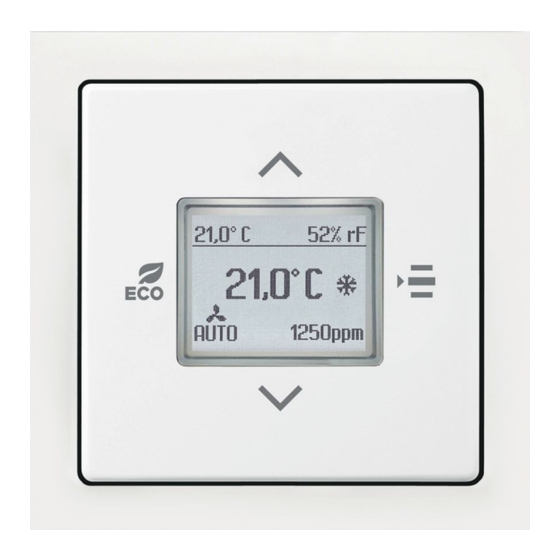
Displayanzeigen
18,5°C
[a]
Ist-Temperatur
[b]
Relative Luftfeuchte
52% rf
[c]
Status Heizen oder Kühlen
[d]
CO
/ Luftdruck
965 ppm
2
[e]
Status FanCoil
Solltemperatur (bei FanCoil
[f]
21,5°C
manuelle Stufeneinstellung)
Weitere Angaben zu Anzeigen und Meldungen siehe Technisches
Handbuch (siehe QR-Code).
Hinweis
Nach einem Reset oder Netzausfall kalibriert sich das Gerät
automatisch neu. Liegen die ersten zuverlässigen Messwerte vor,
schaltet das Gerät auf die Standardanzeige um.
Bedienung
[1] Temperatur erhöhen; Taste drücken.
[2] ECO-Betrieb; Taste drücken.
x
[3] Auswahl einer der folgenden Funktionen in der Reihenfolge der
−
Aufzählung (Taste mehrmals drücken bis Funktion angezeigt
−
wird, dann Auswahl über Pfeiltasten):
Sollwertverstellung
−
■
Aus/Ein
■
−
Lüfterstufen
■
−
■
Umschaltung Heizen / Kühlen
[4] Temperatur verringern: Taste drücken.
Service
Busch-Jaeger Elektro GmbH - Ein Unternehmen der ABB Gruppe,
Freisenbergstraße 2, D-58513 Lüdenscheid,
Tel.: +49 2351 956-1600;
www.BUSCH-JAEGER.com
Switchover to programming mode:
Press all buttons simultaneously for at least 5 seconds.
■
–
The red display illumination becomes active.
–
Display: physical address input
Displays
[a]
Actual temperature
18,5°C
[b]
Relative humidity
52% rf
[c]
Heating or cooling status
[d]
CO
/ air pressure
965 ppm
2
[e]
Fan coil status
Set-point temperature (manual
[f]
21,5°C
stage setting for fan coil)
For additional information on displays and messages, see the
technical reference manual (see QR code).
NOTE
After a reset or a mains failure, the device re-calibrates itself
automatically. When the first reliable measured values are available,
the device switches to the standard display.
Operation
[1] To increase the temperature, press the button.
[2] For ECO mode, press the button.
[3] To select one of the following functions in the sequence of the list
x
(press the button several times until the function is displayed, then
−
select using the arrow buttons):
−
■
Set-point adjustment
Off/on
−
■
Fan speed levels
■
−
Heating/cooling switchover
■
−
[4] To reduce the temperature, press the button.
Service
Busch-Jaeger Elektro GmbH - A member of the ABB Group,
Freisenbergstraße 2, D-58513 Lüdenscheid, Germany,
Tel.: +49 2351 956-1600;
www.BUSCH-JAEGER.com
DE
EN
FR
NL
/
Auto
/
Auto
Werbung

Verwandte Anleitungen für ABB 6109/28-500


Inhaltszusammenfassung für ABB 6109/28-500
- Seite 1 (from ETS 4.2 without additional software). The function is protection type of at least IP 3X (according to DIN EN 60529) or in Busch-Jaeger Elektro GmbH - A member of the ABB Group, – Pull the control elements off only with your hands.
- Seite 2 Les pièces en plastique de l'appareil sont fragiles. logicielle correspondante. Busch-Jaeger Elektro GmbH - Une société du groupe ABB, – Retirer l'élément de commande toujours à la main. Des informations détaillées sur la mise en service et le Freisenbergstraße 2, D-58513 Lüdenscheid,...