Werbung
Quicklinks
GAMMA instabus
Helligkeitsregler
Brightness controller
UP 255/11
5WG1 255-4AB11
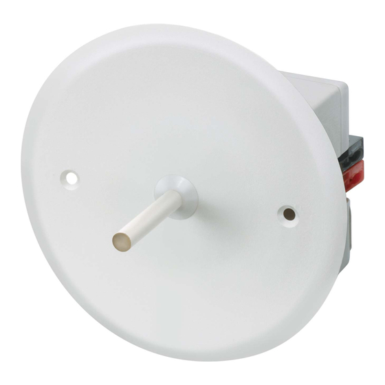
AP 255/12
5WG1 255-4AB12
GE 255/13
5WG1 255-4AB13
Bedien- und Montageanleitung
Operating and Mounting Instructions
Stand: Mai 2012
Issued: May 2012
Bild / Figure 1
Bild / Figure 2
UP 255/11
Bild / Figure 3
AP 255/12
Bild / Figure 4
GE 255/13
Bild / Figure 5
Bild / Figure 6
A5E01251123B
DS 06
D
Produkt- und Funktionsbeschreibung
Die Helligkeitsregler UP 255/11, AP 255/12 und GE 255/13 die-
nen zum Messen und Regeln der Arbeitsplatz- / Raumbeleuch-
tung. Die Regelung kann wahlweise als schaltende Zweipunkt-
Regelung zur Ansteuerung von Schaltaktoren oder als stetige
Konstantlicht-Regelung zur Ansteuerung von Dimmaktoren
bzw. Schalt-/ Dimmaktoren gewählt werden.
Die Regler werden mit jeweils zwei weiß lackierten Lichtleitstä-
ben geliefert. Je nach Bedarf kann der Lichterfassungskegel aus-
gewählt werden. (siehe Montagehinweise auf Seite 2, Bilder
7+8).
Das Applikationsprogramm ist ab der ETS3 ladbar.
Weitere Informationen
http://www.siemens.de/gamma
Lage und Funktion der Anzeige- und Bedienelemente
Gilt für alle Gerätevarianten: (siehe Bild 1)
A1
Busklemme
A2
Inbetriebnahme – Taster
kann auch mit IR-Fernkalibrierung S255 (
ausgelöst werden
A3
Programmier – LED (LED durch den Lichtleiter erkennbar)
Montage und Verdrahtung
Alle Gerätetypen (UP 255/11; AP 255/12; GE 255/13) sind für
feste Installation in trockenen Innenräumen verwendbar.
UP 255/11: (siehe Bild 2)
B1
Deckel
B2
Lichtleitstab (siehe Montagehinweise auf Seite 2, Bild 7+8)
B3
Kunststoffgehäuse
B4
Schrauben zur Befestigung des Unterputzdeckels
B5
Busklemme zum Anschluss der Busleitung (siehe Bild 6)
B6
Lichtleitstabhalter
-
Das Gerät ist zum Einbau in eine Hohlwanddose oder
UP-Dose nach DIN 49073–GB-T-M1E1 (02/90), ∅ 58mm
(Standard), Tiefe 40mm, vorgesehen.
-
Der UP-Helligkeitsregler UP 255/11 wird in Gerätedosen mit-
tels der mitgelieferten Schraubbefestigungen (ohne Krallen)
eingebaut.
AP 255/12: (siehe Bild 3)
C1
Lichtleitstab (siehe Montagehinweise auf Seite 2, Bild 7+8)
C2
Unterteil des Aufputz-Gehäuse
C3
Kunststoffgehäuse
C4
Deckel mit Bajonettverschluss
C5
Busklemme zum Anschluss der Busleitung (siehe Bild 6)
C6
Lichtleitstabhalter
-
Das Gehäuse-Unterteil (∅ 75mm; Höhe = 26 mm) des
AP-Helligkeitsreglers AP255/12 ist über dem Auslass der Bus-
leitung an der Zimmerdecke zu befestigen.
-
Montage / Demontage der Abdeckung mittels Bajonettver-
schluss.
GE 255/13: (siehe Bild 4+5)
D1
Kunststoffgehäuse
D2
Lichtleitstabhalter (∅ 10mm
+-0,1
)
D3
Busklemme zum Anschluss der Busleitung (siehe Bild 6)
D4
doppelseitiges Klebeband (2 Streifen)
D5
Lichtleitstabhalter (siehe Montagehinweise auf Seite 2,
Bild 7+8)
E1
Lichtleitstab (siehe Montagehinweise auf Seite 2,
Bild 7+8)
E2
Lichtleitstabhalter (∅ 10mm
)
+-0,1
E3
Busklemme zum Anschluss der Busleitung (siehe Bild 6)
E4
Kunststoffgehäuse
E5
Leuchtengehäuse / Lichtleistengehäuse
E6
doppelseitiges Klebeband (2 Streifen)
-
Im Leuchtengehäuse ist ein Loch (∅ 10,2mm
hen.
-
In dieses Loch ist der GE255/13 einzulegen und mit dem
doppelseitigen Klebeband zu befestigen.
-
Busleitung anschließen und abklemmen: (siehe Bild 6)
Anschließen der Leitung:
Die Steckklemme (D2) ist für eindrahtige Leiter mit einem
Durchmesser von 0,6... 0,8 mm geeignet.
Die Leiter (D2.4) der Busleitung ca. 5 mm abisolieren und
in die Klemme (D2) stecken. Auf richtige Polarität achten!
Abklemmen der Leitung:
Die Busklemme (D2) abziehen und die Leiter (D2.4) der
Anschlussleitung, bei gleichzeitigem Hin- und Herdrehen,
herausziehen.
Steckklemmen abziehen:
Den Schraubendreher vorsichtig unter die Mitte der Bus-
klemme einführen und die Busklemme aus dem Gehäuse zie-
hen.
ACHTUNG: Beim Entfernen der Busklemme darauf achten,
dass die Stifte durch den Schraubendreher nicht kurzge-
schlossen werden.
Steckklemmen aufstecken:
Die Steckklemme (D2) auf die Kontaktstifte stecken und bis
zum Anschlag in das Gehäuse drücken.
V
GEFAHR
• Bei der Installation ist auf ausreichende Isolierung zwischen
Netzspannung und Bus zu achten! Der Mindestabstand von
4mm zwischen Busleitung (incl. Busklemmenbereich) und
Netzspannungsleitungen ist einzuhalten!
• Das Gerät darf nur von einer zugelassenen Elektrofachkraft
installiert und in Betrieb genommen werden.
• Das Gerät darf nicht geöffnet werden.
Bei der Planung und Errichtung von elektrischen Anlagen sind
die einschlägigen Richtlinien, Vorschriften und Bestimmungen
des jeweiligen Landes zu beachten!
Seite 1 von 2
Product and Applications Description
The brightness controllers UP 255/11, AP 255/12 and GE 255/13
are used for metering and controlling workplace and room
lighting. At the user's discretion, the control can be selected as a
switching On/Off control for controlling switch actuators or as a
continuous constant light level control for controlling dimming
actuators or switch/dimming actuators.
The controllers are delivered with two white-painted optical fi-
bre
rods. Depend on the application can the light measurement
adapted to the application. (see mounting instructions fig.7+8)
For loading the application program the ETS3 has to be used.
Additional information
http://www.siemens.com/gamma
Location and function of the display and operating elements
For all device alternatives: (see figure 1)
A1
Bus terminal
A2 commisioning push button
can also triggered by the IR remote calibration S255
)
5WG1 255-7AB01
(
)
5WG1 255-7AB01
A3
commisioning LED (LED viewable by the fibre rod)
Mounting and wiring
All device alternatives may be used for permanent installation
in dry interior locations.
UP 255/11: (See figure 2)
B1
Cover
B2
Optical fibre rod (see mounting instructions page2,
fig.7+8)
B3
Plastic housing
B4
Screws for fixing the cover
B5
Bus terminal for connecting the bus cable (see fig.6)
B6
fastener for optical fibre rod
-
The system is intended for installation in a cavity wall socket
or flush mounting socket conform to DIN 49073–GB-T-M1E1
(02/90), ∅ 58mm (Standard), depth 40 mm.
-
The flush mounting brightness controller UP 255/11 is
mounted into sockets by means of the screw fixings (without
claws) supplied.
AP 255/12: (See figure 3)
C1
Optical fibre rod (see mounting instructions page2,
fig.7+8)
C2
Bottom part of the housing for surface-mounting
C3
Plastic housing
C4
Cover with bayonet connection
C5
Bus terminal for connecting the bus cable (see fig.6)
C6
Fastener for optical fibre rod
-
The bottom part (∅ 75 mm, height 26 mm ) of the surface
mounting brightness controller AP255/12 is to be fixed to the
ceiling via the outlet for the bus cable.
-
Mounting / Demounting of the cover via a bayonet coupling.
GE 255/13: (See figure 4+5)
D1
Plastic housing
D2
Fastener for optical fibre rod (∅ 10mm
D3
Bus terminal for connecting the bus cable (see fig.6)
D4
double-faced adhesive tape (2 stripes)
D5
Optical fibre rod (see mounting instructions page2,
fig.7+8)
E1
Optical fibre rod (see mounting instructions page2,
fig.7+8)
E2
Fastener for optical fibre rod (∅ 10mm
E3
Bus terminal for connecting the bus cable (see fig.6)
E4
Plastic housing
E5
lamp housing
E6
double-faced adhesive tape (2 stripes)
-
) vorzuse-
±0,1
Make a hole (∅ 10,2mm
-
Take the GE 255/13 in the hole and fix it with the double-
faced adhesive tape in the housing.
Connecting and disconnecting the bus line: (See figure 6)
Connecting the cable:
The bus terminal (D2) is suitable for solid leads with a di-
ameter of 0.6 ... 0.8 mm.
Strip the insulation from the bus leads (D2.4) to a distance
of approx. 5 mm and plug them into the terminal (D2).
Ensure the polarity is correct!
Disconnecting the cable:
Pull off the bus terminal (D2) and pull out the leads (D2.4)
by turning a lead alternately backwards and forwards.
Pulling out the plug-in terminals:
Insert a screwdriver carefully under the centre of the bus
terminal and pull the bus terminal out of the housing.
CAUTION: When removing the bus terminal, be careful not to
short-circuit the pins with the screwdriver.
Plugging in the plug-in terminals:
Push the plug-in terminal (D2) on to the pins and press un-
til it stops in the housing.
V
DANGER
• During installation, ensure adequate insulation between
mains voltage and bus! A minimum spacing should be main-
tained between bus cable cores (also the area round Bus Ter-
minal) and mains voltage cable cores of at least 4mm.
• The device may only be installed and commissioned by a li-
censed electrician.
• The device must not be opened.
When planning and installing electrical installations, the rele-
vant national directives, rules and regulations of the country in
question are to be obeyed.
GB
)
+-0,1
+-0,1
)
±0,1
) in the lamp housing.
page 1 of 2
Werbung

Verwandte Anleitungen für Siemens AP 255/12


Inhaltszusammenfassung für Siemens AP 255/12
- Seite 1 GAMMA instabus Produkt- und Funktionsbeschreibung Product and Applications Description The brightness controllers UP 255/11, AP 255/12 and GE 255/13 Die Helligkeitsregler UP 255/11, AP 255/12 und GE 255/13 die- Helligkeitsregler are used for metering and controlling workplace and room nen zum Messen und Regeln der Arbeitsplatz- / Raumbeleuch- Brightness controller lighting.
- Seite 2 Electrical safety • Schutzart (nach EN 60529): • Protection class (to EN 60529): IP 20 für UP 255/11; AP 255/12; GE 255/13 IP 20 for UP 255/11; AP 255/12; GE 255/13 Die Schutzart IP40 kann für den AP255/12 durch Installation The IP40 degree of protection can be achieved for the auf einer glatten Fläche erreicht werden.