Werbung
Quicklinks
GAMMA wave
Koppler wave / instabus UP 140 (D)
Coupler wave / instabus UP 140 (GB)
5WG3 140-2_B_1
Bedien- und Montageanleitung (D)
Operating and mounting instructions (GB)
Stand: März 2008 (D)
As at: March 2008 (GB)
A
D
Produkt- und Funktionsbeschreibung
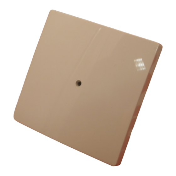
Der Koppler wave / instabus UP 140 (Bild A) verbindet das GAMMA
wave Funksystem mit dem GAMMA instabus. Er ist eine spezielle
Taste wave, die in den Designs der Schalterprogramme DELTA pro-
fil, DELTA style und DELTA i-system verfügbar ist.
Zusammen mit dem zugehörigen Rahmen der Schalterprogramme
wird der Koppler auf einen instabus Busankoppler UP 114 aufge-
steckt (separat zu bestellen).
Die Übertragung arbeitet bidirektional. Dabei werden Meldungen
und Befehle, die über Funk empfangen werden, auf dem instabus
gesendet und umgekehrt, empfangene Bustelegramme über Funk
weitergeleitet.
Mit der Taste des Kopplers ist zusätzlich eine beliebige Bedienfunk-
tion über den instabus und über Funk möglich.
In der Mitte der Taste ist eine LED angebracht, die zur Anzeige von
Telegrammübertragungen und des Programmiermodus des
Kopplers verwendet wird.
Die Programmierung des Kopplers wave / instabus UP 140 sowie
das Verbinden mit anderen Funkkomponenten erfolgt mit Hilfe der
ETS.
Hinweis:
Für den Koppler wave / instabus UP 140 ist ein Busankoppler UP
114 ab Version 2.1 (21R1) zu verwenden.
Weitere Informationen
http://www.siemens.de/gamma
Technische Daten
Frequenzband
• 868 MHz (störunempfindliche Übertragung; Frequenzband für
System- und Sicherheitsanwendungen)
Funkreichweite
• ca. 100 m im Freifeld
Spannungsversorgung
• erfolgt über die Anwenderschnittstelle (AST) des
Busankopplers UP 114
Bedienelemente
• 1 Tasterwippe mit Ruhelage in der Mittelstellung
Anzeigeelemente
• 1 rote LED in der Tastermitte
Anschlüsse
• 10-polige Stiftleiste (AST) zum Anschluss an den Busankoppler
Mechanische Daten
• Abmessungen (L x B x T):
DELTA i-system
55x55x24mm (incl. Feder)
DELTA profil
65x65x25mm (incl. Feder)
DELTA style
68x68x27mm (incl. Feder)
• Gewicht: ca.35g
Elektrische Sicherheit
• Schutzart (nach EN 60529): IP 20
Umweltbedingungen
• Umgebungstemperatur im Betrieb: - 5 ... + 45°C
• Lagertemperatur: - 25 ... + 70°C
• rel. Feuchte (nicht kondensierend): 5% bis 93%
Prüfzeichen
• KNX / EIB
CE-Kennzeichnung
gemäß EMV-Richtlinie (Wohnbau), Niederspannungsrichtlinie, so-
wie R&TTE-Richtlinie
Konformitätserklärung
Hiermit erklärt die SIEMENS AG, dass sich der Koppler wave /
instabus UP 140 in Übereinstimmung mit den grundlegenden An-
forderungen und den anderen relevanten Vorschriften der Richtli-
nie 1999/5/EG befindet.
Die CE-Erklärung kann eingesehen werden bei:
SIEMENS AG
Siemensstraße 10
93055 Regensburg
Montage
Achtung:
• Das Gerät darf nur in Innenräumen und für trockene Räume
verwendet werden.
• Der Einbau des Gerätes in Metallwände ist zu vermeiden, da da-
durch die Funkreichweite erheblich vermindert wird.
• Die Sendereichweite kann vereinzelt durch bauliche Gegeben-
heiten (z.B. Stahlbeton) oder elektrische / elektronische Stör-
quellen beeinflusst werden.
• Zwischen dem Sender und den zugehörigen Empfängern ist ein
Abstand von mindestens 0,5 m einzuhalten.
• Obwohl die Funkübertragung im sicheren 868 MHz-Frequenz-
band erfolgt, können Störungen der Funkübertragung nicht
ausgeschlossen werden.
• Die Funkübertragung ist nicht geeignet für Sicherheitsanwen-
dungen.
Seite 1 von 2
GB
Product and Applications Description
The Coupler wave / instabus UP 140 (Diagram A) connects the
GAMMA wave radio system to the GAMMA instabus. It is a special
pushbutton wave available in the designs of the DELTA profil,
DELTA style and DELTA i-system switch ranges.
The Coupler is plugged together with the corresponding switch
range frame onto an instabus bus coupling unit UP 114 (must be
separately ordered).
Transmission is bidirectional. Messages and commands which are
received by radio are sent on the instabus and vice versa, i.e. re-
ceived bus telegrams are forwarded by radio.
The pushbutton of the coupler enables optional operation by
means of the instabus and radio.
In the middle of the pushbutton is an LED which is used to indicate
telegram transmissions and the programming mode of the cou-
pling unit.
The programming of the Coupler wave / instabus UP 140 and the
connection with other radio components takes place with the help
of the ETS.
Note:
A bus coupling unit UP 114 Version 2.1 (21R1) or higher must be
used for the Coupler wave / instabus UP 140.
Additional Informations
http://www.siemens.com/gamma
Technical data
Frequency band
• 868 MHz (transmission is not susceptible to interference; fre-
quency band reserved for system and security applications)
Range of radio control
• approx. 100 m (applies to free field applications)
Power supply
• via the physical external interface (PEI) of the bus coupling unit
UP 114
Control elements
• 1 pushbutton rocker, idle in middle position
Indicator lamps
• 1 red LED in the middle of the pushbutton
Connections
• 10 pin bar (PEI) for connection to the bus coupling unit
Mechanical data
• Dimensions (L x W x D):
DELTA i-system
55x55x24mm (including spring)
DELTA profil
65x65x25mm (including spring)
DELTA style
68x68x27mm (including spring)
• Weight: approx. 35g
Electrical safety
• Protection (acc. to EN 60529): IP 20
Environmental conditions
• Ambient operating temperature: - 5 ... + 45 C
• Storage temperature: - 25 ... + 70 C
• Relative humidity (non-condensing): 5% to 93%
Markings
• KNX / EIB
CE norm
In accordance with the EMC guideline (residential buildings),
low voltage regulations and R&TTE regulations
Declaration of conformity
SIEMENS AG declares herewith that the coupler wave / instabus
UP 140 comply with the basic requirements and other relevant
regulations of Directive 1999/5/EG.
The CE declaration can be inspected at:
SIEMENS AG
Siemensstrasse 10
D-93055 Regensburg
Mounting
Caution:
• The device may be used for interior installations and in dry
rooms only.
• The installation of the device into metal walls has to be avoided
since through this the range of radio control is reduced consid-
erably.
• Occasionally the transmission range may be influenced by struc-
tural conditions (e.g. reinforced concrete) or electric / electronic
sources of interference.
• A minimum distance of 0.5 m must be maintained between the
transmitter and the relevant receivers.
• Though the radio transmission is carried out in the safe 868
MHz range, disruptions to the radio transmission cannot be ex-
cluded.
• The radio transmission is not suitable for security applications.
Page 1 of 2
Werbung

Verwandte Anleitungen für Siemens GAMMA wave UP 140


Inhaltszusammenfassung für Siemens GAMMA wave UP 140
- Seite 1 R&TTE regulations Konformitätserklärung Declaration of conformity Hiermit erklärt die SIEMENS AG, dass sich der Koppler wave / SIEMENS AG declares herewith that the coupler wave / instabus instabus UP 140 in Übereinstimmung mit den grundlegenden An-...
- Seite 2 • Die Bedienungsanleitung ist dem Kunden auszuhändigen. • The operating instructions must be handed over to the client. • Ein defektes Gerät ist an die zuständige Geschäftsstelle der • Any faulty devices should be returned to your local Siemens Siemens AG zu senden. office.