
Verwandte Anleitungen für Märklin 60972


Inhaltszusammenfassung für Märklin 60972
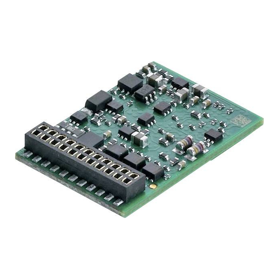
- Seite 1 Nachrüstdecoder-Set 60972 Nachrüstdecoder-Set 60982 60972 Conversion Decoder Set 60982 Conversion Decoder Set...
-
Seite 2: Inhaltsverzeichnis
Inhaltsverzeichnis Seite Table of Contents Page Using the Product as Intended Bestimmungsgemäße Verwendung Lieferumfang Contents as Delivered Sicherheitshinweise Safety Notes Technical Information Technische Daten Funktionen Functions Decoder-Einbau Decoder Installation Multi-Protocol Operation Multiprotokollbetrieb - mfx-Protokoll - mfx-Protocol - fx-Protokoll - fx-Protocol - DCC-Protocol - DCC-Protokoll Physical Functions... -
Seite 3: Bestimmungsgemäße Verwendung
Der mLD LokDecoder, ein LokDecoder mit sehr weit reichenden 1 Klebepad (nur in 60982) Einstell- und Anpassungsmöglichkeiten. Zusätzliche SUSI- Einbauanleitung Schnittstelle (nur bei 60972) steht zur Verfügung. Die Decoder Garantieurkunde sind voll updatefähig. Voraussetzung hierfür ist ein entspre- Für den Einbau zusätzlich benötigtes Werkzeug: Schrauben- chendes Steuergerät (Central Station 60213/60214/60215,... -
Seite 4: Decoder-Einbau
Leiter (blau) anzuschließen. Der gemeinsame Rückleiter (blau) darf nicht mit der Fahrzeugmasse verbunden werden. Die Vorgehensweise ist für den Decoder 60982 und für die Schnitt- stellenplatine aus dem Set 60972 identisch. Bitte beachten Sie jedoch unbedingt die jeweiligen Hinweise zu den Kabelfarben. - Seite 5 60982 chenden Lötpads. Stecken sie den Stecker in die Schnittstelle, Positionierung beachten. Beachten Sie, dass die Kabelfarben am Decoder der NEM Norm Hinweise zur Beleuchtung siehe Decoder 60972. entsprechen. Eine Gegenüberstellung des Märklin-Farbschemas finden Sie nachfolgend. Gegenüberstellung der Kabelfarben grau...
- Seite 6 60972 Decoder einstecken, auf richtigen Einbau achten. Modell noch ohne Gehäuse auf dem Programmiergleis einer Prüfung Halteplatte festschrauben, Kabel entsprechend an die Anschlüs- unterziehen. Wenn der Decoder einwandfrei arbeitet, kann das se von Motor, Schleifer und eventuellen Funktionen löten. Gehäuse montiert werden.
-
Seite 7: Multiprotokollbetrieb
Multiprotokollbetrieb Hinweis: Beachten Sie, dass nicht alle Funktionen in allen Digital-Protokollen möglich sind. Unter mfx und DCC können Analogbetrieb einige Einstellungen von Funktionen, welche im Analog-Betrieb Der Decoder kann auch auf analogen Anlagen oder Gleisab- wirksam sein sollen, vorgenommen werden. schnitten betrieben werden. -
Seite 8: Mfx-Protokoll
mfx-Protokoll startet die Lokomotive langsam, beschleunigt auf höchste Geschwindigkeit und stoppt nach kurzer Zeit. Danach macht Adressierung die Lokomotive mehrere Anfahrversuche. Bleibt die Lokomo- • Keine Adresse erforderlich, jeder Decoder erhält eine einma- tive endgültig stehen, ist das Einmessen beendet. lige und eindeutige Kennung (UID). -
Seite 9: Dcc-Protokoll
• Die Folgeadressen sind ein-, ausschalt- und einstellbar und • Kurze oder lange Adresse wird über die CVs ausgewählt. sind manuell oder automatisch programmierbar. • Eine angewandte Traktionsadresse deaktiviert die Standard- • Über diese vier Adressen sind alle 16 Funktionen schaltbar. Adresse. -
Seite 10: Physikalische Funktionen
Physikalische Funktionen Anfahr-/Bremsverzögerung • Die Beschleunigungs- und Bremszeit kann getrennt von Jede dieser Funktionen muss extern an die Platine angeschlos- einander eingestellt werden. sen werden. Man spricht daher von physikalischen Funktionen. Jedem physikalischem Ausgang (AUX / Licht) kann im Digitalbe- •... -
Seite 11: Cv-Tabelle Fx (Mm)
Decoder Funktionen und CV Einstellungen Nachfolgend finden Sie die Funktionen und die CVs in Tabellen- Das Gleisformat mfx können Sie komfortabel über das Display form aufgeführt. Über diese CVs haben Sie die Möglichkeit eine der CS 2 ab der Software Version 4.0, einstellen. Gegebenenfalls Vielzahl an Einstellungen und die Belegung der Funktionstasten müssen Sie oder Ihr Händler ein Update ihrer Central Station zu ändern. - Seite 12 CV-Tabelle fx (MM) Bedeutung Werte Default Bemerkung Bremsmodus: 0 - 48 Bit 0 - 3 : immer 0, Bremsen richtungsabhängig: Bit 4 : DC Spg., Polarität entgegen der - 16 normales DCC-Verhalten Fahrtrichtung - 32 inverses DCC-Verhalten Bit 5 : DC Spg., Polarität mit der Bremsen richtungsunabhängig: Fahrtrichtung - 48 : fx/mfx - Verhalten...
- Seite 13 CV-Tabelle fx (MM) Werte Bedeutung Default Bemerkung Bit 0: Motor invertiert 1= ein, 0 aus 0 / 1 Bit 1: Licht invertiert 1= ein, 0 aus 0 / 2 Die Werte der benötigten Einstel- Bit 2: Gleis invertiert 1= ein, 0 aus 0 / 4 lungen müssen addiert werden.
- Seite 14 CV-Tabelle fx (MM) Werte Default Bedeutung Bemerkung Verschiedene Zustände speichern: 0 - 7 Bit 0 : Funktionszustände speichern 0 / 1 0 = nicht speichern / 1 = speichern Bit 1 : Geschwindigkeit speichern 0 / 2 0 = nicht speichern / 2 = speichern Bit 2 : Nach Reset mit/ohne ABV anfahren 0 / 4 0 = ohne ABV / 4 = mit ABV...
-
Seite 15: Cv-Tabelle Dcc
CV-Tabelle DCC Bedeutung Werte Default Bemerkung Kurze Adresse 1 - 127 Hauptadresse 1 - 127 Wenn CV29 / Bit 5 = 0 Wert muss kleiner sein als Vmax, CV 5. 2 PoM Minimalgeschwindigkeit (Vmin) 0 - 255 (siehe CV 67) CV-Wert multipliziert mit 0,9 ergibt die 3 PoM Anfahrverzögerung (AV) - Seite 16 CV-Tabelle DCC Bedeutung Werte Default Bemerkung 1 - 127 = Traktionsadresse 0 = keine Traktion Traktionsadresse 0 - 255 +128, Bit 7 = Richtung umpolen bei Traktion 0 = Fkt. # nur für Lokadresse 21 PoM Funktionen F1 - F8 bei Traktion 0 - 255 1 = Fkt.
- Seite 17 CV-Tabelle DCC Bedeutung Werte Default Bemerkung 31 PoM Index high Byte Wird für erweiterte Einstellungen benöti- 32 PoM Index low Byte gt, z.B. CV 300 - 328 Alternative Formate: 0 - 15 Bit 0 : Analog AC aus = 0 / Analog AC ein = 1 0 / 1 Hinweis: 50 PoM...
- Seite 18 CV-Tabelle DCC Bedeutung Werte Default Bemerkung 0 = ungeregelte PWM für Sinus 56 PoM Motorregelung - Regeleinfluss 0 - 255 (siehe auch CV 52 Motortyp) CV-Wert dividiert durch 128 ergibt 66 PoM Vorwärts Trimm 0 - 255 den Faktor, mit dem die Fahrstufe bei Vorwärtsfahrt multipliziert wird.
-
Seite 19: Störungen Beheben
Störungen beheben Entsorgung Bei Betrieb mit verschiedenen Protokollen kann es zu gegensei- Hinweise zum Umweltschutz: Produkte, die mit tigen Störungen kommen: dem durchgestrichenen Mülleimer gekennzeichnet sind, dürfen am Ende ihrer Lebensdauer nicht über – Es wird empfohlen, die Anzahl der Protokolle zu reduzieren. den normalen Haushaltsabfall entsorgt werden, Nicht benötigte Protokolle im Lokdecoder und falls möglich sondern müssen an einem Sammelpunkt für das... -
Seite 21: Meine Persönlichen Decoder-Einstellungen
My personal decoder settings Meine persönlichen Decoder-Einstellungen Locomotive: Lokomotive: Adresse CV - Adress CV - CV - CV - CV - CV - CV - CV - CV - CV - CV - CV - CV - CV - CV - CV - CV - CV -... -
Seite 22: Using The Product As Intended
These instructions describe the installation and the possible set- ed work mat. Failure to do this can lead to dangerous static tings for the 60972 and 60982 decoders. Unless otherwise stated, charge from your body and to damage to the components. -
Seite 23: Decoder Installation
• Automatic calibration of a locomotive with CV 7 (mfx, DCC, MM). This procedure is identical for the 60982 decoder and for the con- nector board from the 60972 set. Make sure that you pay absolute attention to the notes for the colors of the wires for each decoder. - Seite 24 Locomotives or powered rail cars with NEM 8-pin connector. * Currently used only for the programmer. Solder the wires to the correct solder pads according to the diagram above. Insert the plug into the connector while paying attention to the positioning (Information on lighting see Dceoder 60972)
- Seite 25 60972 Plug the decoder into the circuit board and make sure you have plugged it in correctly. Place the model, with the body left off, on Screw down the mounting plate and solder the wires to the the programming track and test it. If the decoder works with no motor connections, pickup(s), and any functions.
-
Seite 26: Multi-Protocol Operation
Multi-Protocol Operation Braking / Signal Stopping Block fx (MM), mfx, DCC The braking module essentially applies DC voltage to the Analog Operation track. If the decoder recognizes a DC voltage of this kind in the This decoder can also be operated on analog layouts or areas of track, it brakes with the delay that has been set. -
Seite 27: Mfx-Protocol
The calibration process can be stopped with the “Stop” Programming button, by turning the speed control knob, by changing the • The characteristics can be programmed using the graphic direction of travel. The process must be repeated after such a screen on the Central Station or also partially with the Mobile termination. -
Seite 28: Dcc-Protocol
Programming Configuration Variables (CV). Reading the CVs is not possible. • The CV numbers and the CV values are entered directly. • The characteristics can be changed repeatedly using the • Program the CVs only on the programming track. Configuration Variables (CV). •... -
Seite 29: Physical Functions
Physical Functions Acceleration/Braking Delay • The acceleration and braking time can be set separately from Each of these functions must be connected externally to the each other. circuit board. We therefore speak of physical functions. A • The logic function ABV can be assigned to any function button unique mode/effect can be assigned to each physical output (AUX / lights) in digital operation. -
Seite 30: Decoder Functions And Cv Settings
Decoder functions and CV settings on the CS 2 with Software Version 2.0 and higher. You or your The following pages have the functions and the CVs presented in dealer may have to install an update on your 60213/60214/60215 tabular form. These CVs can be given a number of settings and Central Station. - Seite 31 CV Table for fx (MM) Values Default Explanation Notes Braking mode: 0 - 48 Bit 0 - 3 : always 0, Braking subject to direction: Bit 4 : DC voltage, polarity against the direction - 16 normal DCC properties of travel - 32 inverse DCC properties Bit 5 : DC voltage, polarity with the direction of Braking not subject to direction:...
- Seite 32 CV Table for fx (MM) Explanation Values Default Notes Bit 0: Motor inverted 1= on, 0 off 0 / 1 Bit 1: Light inverted 1= on, 0 off 0 / 2 The values of the required settings Bit 2: Track inverted 1= on, 0 off 0 / 4 must be added up.
- Seite 33 CV Table for fx (MM) Explanation Values Default Notes 0 - 7 Storing different states: 0 / 1 Bit 0: storing function states 0 = do not store / 1 = store Bit 1: storing speed 0 / 2 0 = do not store / 2 = store Bit 2: starting up with/without ABV after a reset 0 = without ABV / 4 = with ABV 0 / 4...
-
Seite 34: Cv Table For Dcc
CV Table for DCC Explanation Values Default Notes Short address 1 - 127 Main address 1 - 127 If CV 29 / Bit 5 = 0 Value must be lower than Wert muss Minimum speed (Vmin) 0 - 255 Vmax, CV 5. (see CV 67) CV value multiplied by 0.9 gives the time Acceleration delay (AV) 0 - 255... - Seite 35 CV Table for DCC Explanation Values Default Notes 1 - 127 = multiple unit address 0 = no multiple unit Multiple unit address 0 - 255 +128, Bit 7 = reverse polarity for direction when using multiple unit 0 = func. # only for locomotive address Functions F1 - F8 when using multiple unit 0 - 255 1 = func.
- Seite 36 CV Table for DCC Values Explanation Default Notes Alternative formats: 0 - 15 Bit 0 : Analog AC off = 0 / Analog AC on = 1 0 / 1 Note: Bit 1 : Analog DC off = 0 / Analog DC on = 1 0 / 2 DCC cannot deactivate itself.
- Seite 37 CV Table for DCC Values Explanation Default Notes The CV value divided by 128 gives the fac- Forward trim 0 - 255 tor with the speed level is multiplied when the locomotive is running forward. Speed table speed level 1 (Vmin) to 0 - 255 speed table speed level 28 (Vmax) The CV value divided by 128 gives the fac-...
-
Seite 38: Disposing
Troubleshooting Disposing When operating with different protocols you may have problems Products marked with a trash container with a line in each mode at the same time. – We recommend reducing the through it may not be disposed of at the end of their number of protocols. -
Seite 39: Warranty
Warranty The warranty card included with this product specifies the warranty conditions. • Please contact your authorized Märklin dealer for repairs or contact: U.S. only: Märklin, Inc. PO Box 510559 New Berlin WI 53151 Phone: 262-522-7080 Fax: 262-522-7288 Email: info@marklin.com Technical Hotline Contacts: Curtis Jeung &... - Seite 40 Due to different legal requirements regarding electro-magnetic compatibility, this item may be used in the USA only after separate certification for FCC compliance and an adjustment if necessary. Use in the USA without this certification is not permitted and absolves us of any liability. If you should want such certification to be done, please contact us –...
- Seite 41 Ensemble Décodeur de mise à jour 60972 Ensemble Décodeur de mise à jour 60982 Inbouwdecoder-set 60972 Inbouwdecoder-set 60982...
- Seite 42 Sommaire Page Inhoudsopgave Pagina Verantwoord gebruiken Utilisation conforme à sa destination Leveringsomvang Matériel fourni Veiligheidsvoorschriften Remarque sur la sécurité Technische gegevens Caractéristiques techniques Functies Fonctionnement Decoder inbouwen Installation du décodeur Multiprotocolbedrijf Exploitation multiprotocole - mfx-protocol - Protocole mfx - fx-protocol (MM) - Protocole fx (MM) - DCC-protocol - Protocole DCC...
-
Seite 43: Utilisation Conforme À Sa Destination
Utilisation conforme à sa destination peut être à l’origine de courants de choc dangereux et donc de blessures. Les décodeurs 60972/60982 sont destinés à la mise à jour • N’exploiter le décodeur qu’avec la tension admissible des locomotives HO Trix. - Seite 44 • Rapport de manœuvre paramétrable. Ce mode d’emploi décrit l’installation et les possibilités de • Identification de la section de freinage / de signaux réglable des décodeurs 60972/60982. d’arrêt en exploitation numérique. • Capable de gérer plusieurs protocoles (fx (MM), mfx, DCC •...
-
Seite 45: Installation Du Décodeur
Le conducteur de retour (bleu) commun ne doit pas être 7 bleu 3 vert relié à la masse du véhicule. 2 jaune 6 blanche La manière de procéder est la même pour le décodeur 60982 et pour la platine d’interface de l’ensemble 60972. 1 orange grise... - Seite 46 ; respectez le positionnement. de contact et d’éventuelles fonctions. Instructions pour les éclairer le décodeur 60972. Les couleurs des câbles correspondent au standard Märklin, voir tableau comparatif sur les normes NEM.
-
Seite 47: Mode Multiprotocole
Mode multiprotocole lampe à incandescence 610080. Le conducteur de retour est ensuite raccordé au câble orange. Mode analogique Enfi cher le décodeur, veiller à une installation correctement On peut aussi faire fonctionner le décodeur sur des installa- effectuée. Soumettre le modèle à une vérifi cation sur la tions ou des sections de voie analogiques. - Seite 48 mfx/DCC. Le protocole numérique mfx est donc repris par le si vous utilisez des rayons trop petits. Pour la lecture décodeur (voir tableau antérieur). automatique de la locomotive, allez dans la configuration de la locomotive de la Central Station-> CV-> Info. Dans Indication : remarquez que toutes les fonctions ne peuvent le champ Firmware, remplacez le premier nombre par pas être actionnées dans tous les protocoles numériques.
-
Seite 49: Protocole Mfx
• Mappage des fonctions : les fonctions peuvent être Activé (Valeur 77 enregistrée) affectées à de quelconques touches de fonction au Début de la lecture moyen de la station centrale (60212) (restreinte) et avec (vitesse > 1) la station centrale 60213/60214/60215 (voir Aide au niveau de la station centrale). -
Seite 50: Protocole Dcc
• Les paramétrages par défaut (paramétrages usine) Programmation peuvent être rétablis. • Les caractéristiques peuvent être modifiées de façon • 14, voire 27 crans de marche programmables. réitérée par l’intermédiaire des variables de configuration (CVs). • Les quatre premières fonctions et la lumière sont toujours commutables par l’intermédiaire de l’adresse princi- •... -
Seite 51: Fonctions Physiques
Fonctions physiques d’une fonction logique. Chacune de ces fonctions doit être raccordée, extérieure- Retard au démarrage/au freinage ment, à la platine. C’est la raison pour laquelle on parle de • Les temps d’accélération et de freinage peuvent être fonctions physiques. En mode numérique, il est possible paramétrés séparément les uns des autres. -
Seite 52: Tableau Des Valeurs De Configuration Fx (Mm)
Décodeur fonctions et les paramètres CV A partir de la version 4.0 du logiciel, vous pouvez paramétrer confortablement le format de voie mfx par l’intermédiaire Vous trouverez ci-contre, présentées sous la forme de de l’écran de la CS 2. Le cas échéant, il vous faudra, ou tableaux, les fonctions et les CVs. - Seite 53 Tableau des valeurs de configuration fx (MM) Signification Valeurs Par défaut Remarque 1-255 (1 L’adresse peut être dés/activée, en Adresse 4 (3ème adresse de chaînage) - 80)* fonction de la CV 49. Mode de freinage : 0 48 Bit 0 – 3 : Toujours 0 Freinage dépendant de la direction : Bit 4 : tension CC, polarité...
- Seite 54 Tableau des valeurs de configuration fx (MM) Signification Valeurs Par défaut Remarque Formats alternatifs : 0 - 15 Bit 0 : analogique CA hors fonction = 0 0 / 1 analogique CA en fonction = 1 Bit 1 : analogique CC hors fonction = 0 0 / 2 Remarque : Analogique C en fonction = 1...
- Seite 55 Tableau des valeurs de configuration fx (MM) Signification Valeurs Par défaut Remarque 1 - 255 (0 - 63)* Régulation moteur – paramètre de régulation K Partie de régulation K {x4}* 1 - 255 (0 - 63)* Régulation moteur – paramètre de régulation I Partie de régulation I {x4}* 1 - 255 (0 - 63)*...
-
Seite 56: Tableau Des Valeurs De Configuration Dcc
Tableau des valeurs de configuration DCC Signification Valeurs Par défaut Remarque Adresse brève 1 – 127 Adresse principale 1 - 127 Lorsque CV29 / bit 5 = 0 La valeur doit être inférieure à Vmax, CV 5. Vitesse minimale (Vmin) 0 - 255 (voir CV 67). - Seite 57 Tableau des valeurs de configuration DCC Signification Valeurs Par défaut Remarque 0 = # de fonction uniquement pour adresse locomotive Fonctions F1 – F8 pour la traction 0 - 255 1 = # de fonction aussi pour l’adresse de la traction Bit 7 –...
- Seite 58 Tableau des valeurs de configuration DCC Signification Valeurs Par défaut Remarque Index high Byte Requis pour les paramètres avancés, par ex. CV 300 - 328 Index low Byte Formats alternatifs : 0 - 15 Bit 0 : Analogique CA hors fonction = 0 / analo- gique CA en fonction = 1 0 / 1 Bit 1 : Analogique CC hors fonction = 0 / analo-...
- Seite 59 Tableau des valeurs de configuration DCC Signification Valeurs Par défaut Remarque La valeur de la CV divisée par 128 donne le Limitation de la vitesse avant (« Forward trim ») 0 - 255 facteur avec lequel le cran de marche est multiplié...
-
Seite 60: Eliminer Les Perturbations
Eliminer la perturbation Elimination En cas d’exploitation avec différents protocoles, des pertur- Indications relatives à la protection de bations réciproques peuvent se produire. – Il est recom- l’environnement : Les produits marqués du mandé de réduire le nombre des protocoles. Désactiver les signe représentant une poubelle barrée ne protocoles non nécessaires dans le décodeur de locomotive peuvent être éliminés en fin de vie via les... -
Seite 61: Mes Programmations Personnelles Du Décodeur
Mes programmations personnelles du décodeur Mijn persoonlijke decoder instellingen Locomotieves : Locomotief: Adresse CV - CV - CV - CV - CV - CV - CV - CV - CV - CV - CV - CV - CV - CV - CV - CV - CV -... -
Seite 62: Verantwoord Gebruiken
De mLD Decoder is een decoder met zeer veel instel- en Voor het inbouwen heeft men daarnaast de volgende aanpassingsmogelijkheden. Extra SUSI-interface beschik- baar is (slechts 60972). De decoder kan worden geüpdatet. gereedschappen nodig: schroevendraaier, pincet en solde- Hiervoor is een geschikt besturingsapparaat (Central erstation met een soldeertemperatuur van max. -
Seite 63: Decoder Inbouwen
Decoder inbouwen • De optrek- en afremvertraging kunnen apart van elkaar ingesteld worden. Via de functiemapping kan elke Voor het inbouwen van de decoder dient men eerst de gewenste functietoets toegewezen worden. elektrische- en mechanische werking van de locomotief te •... - Seite 64 NEM-norm. Een vergelijkingstabel t.o.v. het Märklin desbetreffende soldeer velden. Steek de decoder in de stek- kleurenschema vindt u hiernaast. ker, let op de juiste positie. Informatie over de verlichting te zien decoder 60972. grijs Motoruitgang 2 Vergelijkingstabel voor de draadkleuren...
- Seite 65 60972 De decoder op de stekker steken, let op de juiste inbouw. Model zonder de kap op het programmeerspoor plaatsen Bevestigingsplaat vastschroeven, draden volgens schema voor het testen. Als de decoder goed functioneert kan de op de motor, sleper en eventuele functies aansluiten.
-
Seite 66: Multiprotocolbedrijf
Opmerking: let er op dat niet alle functies in alle digitaal- Multiprotocolbedrijf protocollen mogelijk zijn. Onder mfx of DCC kunnen enkele Analoogbedrijf instellingen, welke in analoogbedrijf werkzaam moeten zijn, De decoder kan ook op analoge modelbanen of spoortra- ingesteld worden. jecten gebruikt worden. -
Seite 67: Mfx-Protocol
dat op in de loc. Stel met de rijregelaar een snelheid in. Nu trekt de loc langzaam op tot de maximumsnelheid Mfx-protocol en stopt na korte tijd. Daarna maakt de loc meerdere optrekproeven. Blijft de loc langere tijd stilstaan, dan is Adressering het inmeten beëindigt. -
Seite 68: Dcc-Protocol
DCC-protocol • Hoofdadres is handmatig programmeerbaar • De volgadressen zijn in- uitschakel- en instelbaar en zijn Adressering handmatig of automatisch programmeerbaar. • Kort adres – lang adres – tractie adres • Via deze vier adressen zijn alle zestien functies te scha- •... -
Seite 69: Fysieke Functies
motief mogelijk. De rangeerstand kan bij mfx of DCC d.m.v. • Alle functies kunnen overeenkomstig de functiemapping functiemapping aan elke gewenste functietoets worden geschakeld worden (zie CV-beschrijving). toegewezen. Het opzetten van de rangeerstand (zie CV tabel • Voor verdere informatie, zie de CV-tabel DCC-protocol. op pagina 38) CV 145 of MFX in het menu Centraal Station). -
Seite 70: Schakelbare Functies
f0 f8 Schakelbare functies systems STOP mobile station Digital/Systems Frontverlichting function/off Functie f0 Functie f0 Aux 1 Functie 1 Functie * Functie f1 Functie f1 Aux 2 Functie 2 Functie * Functie f2 Functie f2 Rangeerstand Functie 3 Functie * Functie f3 Functie f3 ABV uit... -
Seite 71: Cv-Tabel Fx (Mm)
Decoder functies en CV instellingen Het railformaat mfx kunt u comfortabel via het display van het CS 2, vanaf softwareversie 4.0, instellen. Indien nodig Verderop vindt u de functies en de CV’s in tabelvorm moet u of uw handelaar een update van uw Central Station weergegeven. - Seite 72 CV-tabel fx (MM) Omschrijving Waarde Default Opmerking Afremmodus: 0 - 48 Rijrichting afhankelijk afremmen: Bit 0 - 3 : altijd 0 - 16 normaal DCC gedrag Bit 4 : Polariteit tegen de rijrichting in - 32 omgekeerd DCC gedrag Bit 5 : DC , Polariteit overeenkomstig de Afremmen onafhankelijk van de rijrichting: rijrichting...
- Seite 73 CV-tabel fx (MM) Omschrijving Waarde Default Opmerking Bit 0: motor geïnviteerd 1=aan, 0 uit 0 / 1 De waarden van de benodigde Bit 1: licht geïnviteerd 1=aan, 0 uit 0 / 2 instellingen moet bij elkaar opgeteld Bit 2: rail geïnviteerd 1=aan, 0 uit 0 / 4 worden.
- Seite 74 CV-tabel fx (MM) Omschrijving Waarde Default Opmerking Verschillende toestanden opslaan: 0 - 7 Bit 0 : functie toestanden opslaan 0 / 1 0 = niet opslaan / 1 = opslaan Bit 1 : snelheid opslaan 0 / 2 0 = niet opslaan / 2 = opslaan Bit 2 : na een reset met/zonder ABV wegrijden 0 / 4 0 = zonder ABV / 4 = met ABV...
-
Seite 75: Cv-Tabel Dcc
CV-tabel DCC Omschrijving Waarde Opmerking Default Hoofdadres 1 - 127 Kort adres 1 – 127 als CV29 / Bit 5 = 0 Waarde moet kleiner zijn dan Vmax, CV Minimumsnelheid (Vmin) 0 - 255 5. (zie CV 67) CV-waarde vermenigvuldigd met 0,9 geeft Optrekvertraging (AV) 0 - 255 de tijd van stilstand tot de maximums-... - Seite 76 CV-tabel DCC Omschrijving Waarde Default Opmerking 1 - 127 = Tractieadres 0 = geen tractie Tractieadres 0 - 255 +128, bit 7 = richting ompolen bij tractie 0 = funct. # alleen voor locadres Functies F1 - F8 bij tractie 0 - 255 1 = funct.
- Seite 77 CV-tabel DCC Omschrijving Waarde Default Opmerking Index hoge byte Is nodig voor verdere instellingen bijv. CV 300 - 328 Index lage byte Alternatief formaat: 0 - 15 Bit 0: analoog AC uit = 0 / analoog AC aan = 1 0 / 1 Opmerking: 0 / 2...
- Seite 78 CV-tabel DCC Omschrijving Waarde Opmerking Default De CV-waarde gedeeld door 128 geeft Vooruit trimmen 0 - 255 de factor waarmee de rijstap bij het vooruitrijden vermenigvuldigd wordt. Snelheidstabel rijstap 1 (Vmin) 0 - 255 Snelheidstabel rijstap 28 (Vmax) De CV-waarde gedeeld door 128 geeft de Achteruit trimmen 0 - 255 factor waarmee de rijstap bij het achte-...
-
Seite 79: Storingen Verhelpen
Storingen verhelpen Afdanken Bij het bedrijf met verschillende protocollen kan er onder- Aanwijzing voor de bescherming van het milieu: linge verstoring ontstaan. Het is aan te bevelen, het aantal Producten die voorzien zijn van een merkteken protocollen te reduceren. De niet benodigde protocollen in met een doorgekruiste afvalcontainer, mogen de locdecoder en eventueel ook in de centrale deactiveren. - Seite 80 Due to different legal requirements regarding electro-magnetic compatibility, this item may be used in the USA only after separate certification for FCC compliance and an adjustment if necessary. Use in the USA without this certification is not permitted and absolves us of any liabili- ty.
- Seite 81 Set de decoder de retroequipamiento 60972 Set de decoder de retroequipamiento 60982 Corredo di trasformazione con Decoder 60972 Corredo di trasformazione con Decoder 60982...
- Seite 82 Índice Página Elenco del contenuto Pagina Uso previsto Impiego commisurato alla destinazione Alcance de suministro Corredo di fornitura Advertencias de seguridad Avvertenze di sicurezza Datos técnicos Dati tecnici Funciones Funzioni Montaje del decoder Montaggio del Decoder Funcionamiento multiprotocolo Esercizio multi-protocollo - Protocolo mfx - Protocollo mfx - Protocolo fx...
-
Seite 83: Uso Previsto
≤ 300 mA • Carga AUX + luz (suma) 1 decoder • Carga de motor o bien AUX 5/6 ≤ 1,1 A 1 platina con interfaz de 21 polos (solo en el 60972) • Carga total máx. (suma) ≤ 1,6 A 1 conector NEM de 8 polos (solo en el 60982) ≤ 40 V • Tensión máx. -
Seite 84: Montaje Del Decoder
• Aptos para multiprotocolo (fx (MM), mfx, DCC y AC/DC). • Calibración automática de la locomotora con la variable CV7 (mfx, DCC, MM). • Reconocimiento automático del sistema. Para su manejo, se debe utilizar la dirección asignada en cuestión a este Montaje del decoder sistema. Antes de su montaje, asegurarse de que la locomotora funcione • El retardo de aceleración y frenado se pueden configurar perfectamente desde el punto de vista tanto mecánico como conindependencia uno del otro. Se puede asignar mediante eléctrico. - Seite 85 60972 es idéntico. Terminales soldables arriba Terminales soldables abajo No obstante, no olvide observar las advertencias correspon- dientes sobre los colores de los cables. 8 rojo 4 negro 60982 7 azul 3 verde Tenga presente que los colores de los cables del decoder cumplen la norma NEM.
- Seite 86 Comparativa de los colores de los cables 60972 Atornillar fi rmemente la placa soporte y soldar los cables a las Color de cable Designación conexiones de motor, patín y posibles funciones integradas. Märklin Los colores de los cables cumplen el estándar de Märklin, Conexión de motor 2...
-
Seite 87: Funcionamiento Multiprotocolo
Enchufar el decoder y asegurar que se haya montado correc- Funcionamiento multiprotocolo tamente. Además, someter a una prueba más el modelo en mi- Modo analógico niatura sin carcasa sobre la vía de programación. Si el decoder El decoder se puede utilizar también en maquetas o tramos de funciona sin anomalías, se puede montar la carcasa. vía analógicos. - Seite 88 mfx (véase tabla anterior). el valor allí indicado con el número 77 y guárdelo en la locomotora. Nota: Tenga presente que no todas las funciones son posibles Predefina una velocidad con el regulador de marcha. en todos los protocolos digitales. En mfx y DCC se pueden Ahora, la locomotora arranca lentamente y acelera a realizar algunas configuraciones de funciones que deben tener la velocidad máxima, deteniéndose al cabo de poco efecto en modo analógico.
-
Seite 89: Protocolo Mfx
Protocolo fx (MM) Encontrará información detallada al respecto en Internet: http://www.maerklin.de/de/service/technische-informationen Direccionamiento Protocolo mfx • 4 direcciones (una dirección principal y 3 direcciones sucesi- vas) Direccionamiento • Intervalo de direcciones: • No se requiere ninguna dirección, asignándose a cada 1 - 255 en función de la unidad de control/central decoder un código único e inequívoco (UID). • La dirección principal se puede programar manualmente. • El decoder inicia sesión automáticamente en una Central • Las direcciones sucesivas se pueden activar, desactivar y Station o Mobile Station con su UID. configurar y su programación puede ser manual o automáti- Programación • Las propiedades se pueden programar mediante la interfaz • Estas cuatro direcciones permiten controlar las 16 funciones. -
Seite 90: Protocolo Dcc
desactivada de nuevo permanentemente o si puede controlar- • Pueden configurarse 14 o bien 28/126 niveles de marcha. se mediante una de las direcciones sucesivas. Este mapeo de • Para el frenado automático recomendamos configurar en funciones puede definirse solo en el protocolo mfx o DCC. el modo DCC el valor de la CV 27 a 16 o 32 (véase página • Para información adicional, véase la Tabla de CVs del proto- 20). -
Seite 91: Funciones Físicas
Funciones físicas Retardo de arranque/frenado • Los tiempos de aceleración y frenado se pueden configurar Cada una de estas funciones debe conectarse externamente a la platina. Por este motivo, se habla de funciones físicas. A cada uno independiente del otro. salida física (AUX / Luces) se puede asignar un modo/efecto • La desactivación de la función lógica de retardo de acelera- propio en funcionamiento en modo digital. Para ello están dis- ción y frenado (ABV) se puede asignar a cualquier tecla de ponibles tres CVs para cada salida. Para cada salida se puede función mediante el mapeo de funciones. - Seite 92 Funciones del decodificador y la configuración de CV A continuación encontrará funciones y las CVs en forma de Puede configurar el formato de vía mfx cómodamente desde el tabla. Mediante estas CVs puede modificar un gran número de display de la CS 2 a partir de la versión de software 4.0. En su parámetros y la asignación de funciones a las teclas de función. caso, usted o su distribuidor puede realizar una actualización de su Central Station 60213/60214/60215.
- Seite 93 La tabla CV fx (MM) Significado Valores V.defecto Observación Modo de frenado: 0 - 48 Frenado en función de sentido de marcha: Bit 0- 3 : siempre 0, - 16 respuesta DCC normal DCC Bit 4 : Tensión DC, polaridad opuesta al sentido - 32 respuesta DCC inversa de marcha Frenado independiente del sentido de Bit 5 : Tensión DC, polaridad idéntica al sentido marcha: de marcha...
- Seite 94 La tabla CV fx (MM) CV Significado Valores V.defecto Observación Formatos alternativos: 0 - 15 Bit 0 : Analógico AC desactivado = 0 / analó- gico AC activado = 1 0 / 1 Nota: Bit 1 : Analógico DC desactivado = 0 / analó- fx (MM) no puede desactivarse por gico DC activado = 1 0 / 2 sí solo. Bit 2: DCC desactivado = 0 /DCC activado = 1 0 / 4 Bit 3 : mfx desactivado = 0 / mfx activado = 1 0 / 8 0 / 1...
- Seite 95 La tabla CV fx (MM) CV Significado Valores V.defecto Observación 0-255 (0 - 63)* Regulación del motor: parámetro de regulación I Componente de regulación integral I {x4}* 0-255 (0 - 63)* 0 = PWM no regulado para Sinus Regulación del motor: influencia en la regulación {x4}* (véase además CV 52 Tipo de motor) Guardar diferentes estados: 0 - 7 Bit 0: Guardar estados de funciones 0 = no guardar/ 1 = guardar 0 / 1 Bit 1: Guardar velocidad 0 = no guardar/ 2 = guardar 0 / 2 Bit 2: Tras un reset arrancar con/sin el retardo de 0 = sin retardo arra/frena 4 = con...
-
Seite 96: La Tabla Cv Dcc
La tabla CV DCC Significado Valores V.defecto Observación Dirección corta 1 – 127 Dirección principal 1 - 127 cuando CV29 / bit 5 = 0 El valor debe ser menor que Vmáx, CV 5. Velocidad mínima (Vmín) 0 - 255 (véase CV 67) El valor de CV multiplicado por 0,9 Retardo de arranque (AV) 0 - 255 arroja el tiempo desde el reposo hasta la velocidad máxima. - Seite 97 La tabla CV DCC Significado Valores V.defecto Observación 1 - 127 = Dirección de tracción 0 = sin tracción Dirección de tracción 0 - 255 +128, bit 7 = Invertir sentido cuando haya tracción 0 = Fcn. # solo para dirección de loco Funciones F1 - F8 en tracción 0 - 255 1 = Fcn.
- Seite 98 La tabla CV DCC Significado Valores V.defecto Observación Índice, byte de mayor peso Índice, byte de menor peso Índice, byte de menor peso Formatos alternativos: 0 - 15 Bit 0 : Analógico AC desact= 0 / Analógico AC act. = 1 0 / 1 Nota: Bit 1 : Analógico DC desact. = 0 / Analógico DC act = 1 0 / 2 DCC no puede desactivarse a sí Bit 2 : fx (MM) desact = 0 / fx (MM) act. = 1 0 / 4 mismo.
- Seite 99 La tabla CV DCC Significado Valores V.defecto Observación El valor de CV dividido por 128 arroja el Corrección de marcha adelante 0 - 255 factor por el cual se multiplica el nivel de marcha en marcha hacia adelante. Tabla de velocidades Nivel de marcha 1 (Vmín) hasta 0 - 255 Tabla de velocidades Nivel de marcha 28 (Vmáx) El valor de CV dividido por 128 arroja el...
-
Seite 100: Solución De Anomalías
Solución de anomalías Eliminación En el funcionamiento con diferentes protocolos pueden produ- Indicaciones para la protección del medio ambien- cirse perturbaciones e interferencias mutuas. Se recomienda te: Los productos identificados con el contenedor reducir el número de protocolos. Desactivar los protocolos que de basura tachado no deben eliminarse como no se necesiten en el decoder de locomotora y, si es posible, basura doméstica normal y corriente al final de la... - Seite 101 Le mie impostazioni personali dei Decoder Mi configuración personal del decoder Locomotive: La locomotora: Dirección CV - CV - CV - CV - CV - CV - CV - CV - CV - CV - CV - CV - CV - CV - CV - CV -...
-
Seite 102: Impiego Commisurato Alla Destinazione
≤ 300 mA 1 Decoder • Carico motore risp. AUX 5/6 ≤ 1,1 A 1 circuito stampato con interfaccia a 21poli (solo in 60972) ≤ 1,6 A • Max. carico complessivo (somma) 1 spina a innesto NEM a 8 poli (solo in 60982) • Max. tensione ≤ 40 V 1 piastra di fi ssaggio (solo in 60972) • Protezione da corto circuito e da sovraccarico alle uscite luci... -
Seite 103: Montaggio Del Decoder
Il modo di procedere è identico per il Decoder 60982 e per il • Calibrazione automatica della locomotiva con CV7 (mfx, DCC, circuito stampato di interfaccia proveniente dal corredo 60972. MM). Vi preghiamo comunque di prestare attenzione assolutamente alle rispettive Avvertenze sui colori dei cavetti. - Seite 104 Inserite la spina a innesto der corrispondono alle norme NEM. Potete trovare qui di seguito nell’interfaccia, Fate attenzione al posizionamento. Avvertenze una comparazione dello schema dei colori Märklin. sull’illuminazione si veda il Decoder 60972/60982. grigio connessione 2 al motore Comparazione dei colori dei cavetti nero...
- Seite 105 60972 Innestare il Decoder, si presti attenzione al corretto montaggio. Sottoporre il modello a un collaudo sul binario di programmazi- Fissate con vite la piastra di supporto, saldate i cavetti in one ancora senza mantello. Quando il Decoder funziona senza corrispondenza alle connessioni di motore, pattino ed eventuali inconvenienti, il mantello può...
-
Seite 106: Esercizio Multi-Protocollo
Esercizio multi-protocollo sono possibili in tutti i protocolli Digital. Sotto mfx e DCC possono venire predisposte alcune impostazioni di funzioni, le quali Esercizio analogico devono essere efficaci nell’esercizio analogico. Il Decoder può venire messo in funzione anche su impianti Sezione di frenatura/arresto al segnale fx (MM), mfx, DCC analogici oppure su sezioni di binario. -
Seite 107: Protocollo Mfx
Adesso la locomotiva si avvia lentamente ed accelera alla più Protocollo mfx alta velocità e si arresta dopo un breve tempo. Dopodiché la Indirizzamento locomotiva compie numerose prove di avviamento. Quando la locomotiva rimane finalmente ferma, la calibrazione è • Nessun indirizzo necessario, ciascun Decoder riceve un’identità unica e inconfondibile (UID). terminata. Durante tutto quanto il procedimento non si deve intervenire. -
Seite 108: Protocollo Dcc
1 - 255 in dipendenza dall’apparato di comando/centrale • Per ulteriori informazioni, si veda la tabella delle CV, protocol- lo fx. • L’ indirizzo primario è programmabile manualmente1 - 255 • Gli indirizzi in successione sono attivabili, disattivabili ed Protocollo DCC impostabili e sono programmabili in modo manuale o auto- matico. Indirizzamento • Mediante questi quattro indirizzi sono commutabili tutte le 16 • Indirizzo breve – indirizzo lungo – indirizzo trazione multipla funzioni. • Campo degli indirizzi: 1 - 127 indirizzo breve, indirizzo trazione multipla 1 - 10239 indirizzo lungo Programmazione • Ciascun indirizzo è programmabile manualmente. • Le caratteristiche del Decoder possono venire programmate • L’indirizzo breve oppure lungo viene selezionato tramite le CV. -
Seite 109: Funzioni Fisiche
DCC di impostare il valore in CV 27 su 16 oppure 32 (si veda a patura di funzione può venire disposta su ciascun tasto di pagina 36). funzione a piacere. • Tutte le funzioni possono venire commutate in modo corris- Andatura da manovra (RG) pondente alla mappatura delle funzioni (si veda le descrizione • L’andatura da manovra effettua una riduzione della velocità... - Seite 110 f0 f8 Funzioni commutabilis systems STOP mobile station Digital/Systems Segnale di test function/off Funzione f0 Funzione f0 Aux 1 Funzione 1 Funzione * Funzione f1 Funzione f1 Aux 2 Funzione 2 Funzione * Funzione f2 Funzione f2 Andatura da manovra Funzione 3 Funzione * Funzione f3...
- Seite 111 Decoder per funzioni ed impostazioni CV Qui di seguito potete trovare le funzioni e le CV presentate in Il formato di binario mfx lo potete impostare comodamente forma di tabella. Tramite queste CV Voi avete la possibilità di tramite lo schermo visore della CS 2 a partire dalla Versione Sof- modificare una gran quantità di impostazioni e l’assegnazione tware 4.0. Se necessario, Voi oppure il Vostro fornitore dovete dei tasti funzione.
- Seite 112 Tabella CV fx (MM) Significato Valori Default Annotazioni 0 - 48 Modalità di frenatura: Bit 0 - 3 : sempre 0 Frenatura dipendente dalla direzione: Bit 4 : t ens. DC, polarità contraria al senso di - 16 comportamento DCC normale marcia - 32 comportamento DCC inverso Bit 5 : t ens. DC, polarità concorde al senso di Frenatura dipendente dalla direzione: marcia - 48 comportamento fx/mfx Bit 6 - 7 : sempre 0...
- Seite 113 Tabella CV fx (MM) Significato Valori Default Annotazioni 0 / 1 Bit 0: Motore invertito 1= attivo, 0 spento 0 / 2 Bit 1: Fanali invertiti 1= attivo, 0 spento I valori delle impostazioni necessarie Bit 2: Binario invertito 1= attivo, 0 spento 0 / 4 devono venire sommati. Bit 3: Aux 3 (1= logica, 0= uscita potenziata) 0 / 8 Bit 4: Aux 4 (1= logica, 0= uscita potenziata) 0 / 16 Tipo di motore (Bit 0-4) 0 - 7 Scelta di un tipo di motore per ulteriore Aux – uscite di funzioni 5 e 6 impostazione della regolazione del Motore - Softdrive Sinus motore.
- Seite 114 Tabella CV fx (MM) CV Significato Valori Default Annotazioni Memorizzare le diverse condizioni: 0 - 7 Bit 0 : Memorizzare le condizioni delle funzioni 0 / 1 0 = non memorizza / 1 = memorizza Bit 1 : Memorizzare la velocità 0 / 2 0 = non memorizza / 2 = memorizza Bit 2 : Dopo ripristino avviare con/senza ABV 0 / 4 0 = senza ABV / 4 = con ABV Memorizzare le diverse condizioni: 0 - 1 0 = non memorizza / 1 = memorizza Bit 0 : Memorizzare il senso di marcia 1 - 255 L’indirizzo può venire disattivato, in Indirizzo 2 (1° indirizzo concatenato) 1 - 80* dipendenza dalla CV 49.
- Seite 115 Tabella CV DCC Significato Valori Default Annotazioni Indirizzo breve 1 - 127 Indirizzo principale 1 - 127 quando CV29 / Bit 5 = 0 Il valore deve essere minore di Vmax, CV5. Velocità minima (Vmin) 0 - 255 (si veda CV 67) Il valore della CV moltiplicato per 0,9 dà il Ritardo di avviamento (AV) 0 - 255 tempo da stato fermo sino alla massima...
- Seite 116 Tabella CV DCC Significato Valori Default Annotazioni 1 - 127 = indirizzo unità di trazione 0 = nessuna unità di trazione Indirizzo unità di trazione 0 - 255 +128, Bit 7 = inverte polarità nell’unità di trazione 0 = Funz. # solo per indirizzo locomotiva Funzioni F1 - F8 con unità di trazione 0 - 255 1 = Funz.
- Seite 117 Tabella CV DCC Significato Valori Default Annotazioni Indice high Byte È necessario per impostazioni estese, ad es. CV 300 - 328 Indice low Byte Formati alternativi: 0 - 15 Bit 0 : Analogico AC inattivo = 0 / Analogico AC attivo = 1 0 / 1 Avvertenza: Bit 1 : Analogico DC inattivo = 0 / Analogico DC attivo = 1 0 / 2 DCC non può disattivarsi da solo. Bit 2 : fx (MM) inattivo = 0 / fx (MM) attivo = 1 0 / 4 Bit 3 : mfx inattivo = 0 / mfx attivo = 1 0 / 8 Bit 0: Motore invertito 1= attivo, 0 spento 0 / 1 Bit 1: Fanali invertiti 1= attivo, 0 spento...
- Seite 118 Tabella CV DCC Significato Valori Default Annotazioni Il valore della CV diviso per 128 dà il fattore Taratura in avanti 0 - 255 con il quale la gradazione di marcia viene moltiplicata in caso di marcia avanti. Tabella delle velocità gradazione di marcia 1 (Vmin) sino 0 - 255 a tabella delle velocità...
-
Seite 119: Smaltimento
Smaltimento Eliminazione dei difetti. Avvertenze per la protezione ambientale: I prodotti Durante il funzionamento con differenti protocolli si può che sono contraddistinti con il bidone della spaz- pervenire a disturbi reciproci. - È consigliabile ridurre il numero zatura cancellato alla fine della loro durata di vita dei protocolli. - Seite 120 Due to different legal requirements regarding electro-magnetic compatibility, this item may be used in the USA only after separate certification for FCC compliance and an adjustment if necessary. Use in the USA without this certification is not permitted and absolves us of any liability. If you should want such certification to be done, please contact us – also due to the additional costs incurred for this. Gebr. Märklin & Cie. GmbH Stuttgarter Str. 55 - 57 73033 Göppingen 260184/0516/Sc2Ef Germany...
- Seite 121 Konverteringsdekoder-sats 60972 Konverteringsdekoder-sats 60982 Omstillingsdekodersæt 60972 Omstillingsdekodersæt 60982...
- Seite 122 Innehållsförteckning Sidan Indholdsfortegnelse Side Avsedd användning Hensigtsmæssig anvendelse Satsens innehåll Leveringsomfang Säkerhetsföreskrifter Sikkerhedsvejledninger Tekniska data Tekniske data Funktioner Funktioner Installation av dekoder Dekodermontage Multiprotokollfunktioner Multiprotokoldrift - mfx-protokoll - mfx-protokol - fx-protokoll - fx-protokol - DCC-protokoll - DCC-protokol Fysiska funktioner Fysiske funktioner Logiska funktioner Logiske funktioner Manövererbara funktioner...
-
Seite 123: Satsens Innehåll
Användningsområde Tekniska data Dekodrarna 60972/60982 är avsedda för konvertering av Märklin/ • Kontinuerlig beslastning av motoranslutning ≤ 1,1 A Trix H0-lokomotiv. • Belastning av belysningsanslutning ≤ 250 mA vardera ≤ 250 mA • Belastning AUX 1 - AUX 4 ! Inte avsedd för motorer med fältspole. Lok med sådana motorer •... -
Seite 124: Installation Av Dekoder
LED-anoden (+) ansluts till den gemensamma ledaren (blå). Den gemensamma återkopplingen (blå) får absolut inte kopplas ihop med fordonets jord. Monteringen av dekoder 60982 och kontaktkortet till dekoder 60972 genomförs på samma sätt. Observera: Följ alltid de medföljande instruktionerna avseende kabelfärgerna. - Seite 125 Följ ovanstående schema och löd fast kablarna vid respektive vandlingsschema för motsvarande färger i Märklins färgschema lödpunkt. Var noggrann med att kontakten sätts i åt rätt håll. visas här intill. Beträffande belysning: Se dekoder 60972/60982. grå Motoranslutning 2 Omvandlingsschema för kabelfärgerna svart Strömupptagning räls vänster...
- Seite 126 60972 Var noggrann med att sticka i dekodern ordentligt och åt rätt håll. Provkör modellen på Programmeringsspåret - med kåpan Skruva fast kontaktplattan, löd fast kablarna till motoranslutnin- avmonterad. När dekodern fungerar felfritt kan kåpan åter gar, släpsko och eventuella funktioner.
- Seite 127 Multiprotokoll-drift ställningar av funktioner som ska vara aktiva vid analog körning. Analog drift Inbromsnings-/signalstoppsavsnitt fx (MM), mfx, DCC Dekodern kan även användas på analoga anläggningar eller Inbromsningsmodulen matar huvudsakligen rälsen med en spåravsnitt. Dekodern känner automatiskt av och anpassar sig likspänning.
-
Seite 128: Mfx-Protokoll
Om Stop aktiveras, körvredet manövreras (0) eller lokets Programmering körriktning ändras, avbryts kalibreringen som då måste göras • Egenskaperna kan programmeras via Central Stations grafis- om från början. ka gränssnitt samt delvis även göras med Mobile Station. Är man inte nöjd med kalibreringen kan man prova att kalibre- •... -
Seite 129: Dcc-Protokoll
• CV-nummer och CV-värden matas in direkt. Programmering • Programmering av CV-värden får endast göras på program- • Egenskaperna kan varieras på ett flertal sätt via konfigura- meringsspåret. tions-variablerna (CV). • Återställning av inställningarna (till fabriksinställningar) kan • CV-nummer och CV-värden skrivs in direkt. göras. -
Seite 130: Fysiska Funktioner
Fysiska funktioner Accelerations-/inbromsningsfunktioner Var och en av dessa funktioner måste anslutas externt på kortet. • Accelerations- och inbromsningstider kan ställas in separat Dessa kallas därför fysiska funktioner. Varje fysisk utgång (AUX/ från varandra. belysning) kan vid digital körning tilldelas en egen effekt. För •... - Seite 131 Decoder-funktioner och CV-inställningar Format mfx kan man enkelt ställa in via displayen på sin CS2 fr.o.m. mjuvara/software Version 4.0. Om denna version ej finns Här nedan återfinns dekoderns funktioner och dekoderns CVn i installerad, så måste man själv - eller kostnadsfritt med hjälp av tabellform.
- Seite 132 CV-Tabelle fx (MM) CV Betydelse Värden Default Anmärkning 0 - 48 Bromsinställning: Bromsar körriktningsberoende: Bit 0-3 : alltid 0 -16 normala DCC-värden Bit 4 : DC Spg., Polaritet motsatt färdrikt -32 inverterade DCC-värden ningen Bromsar körriktnings-oberoende: Bit 5 : DC Spg, Polaritet med körriktningen -48 :fx/mfx - värden Bit 6 - 7 : alltid 0 Konfiguration:...
- Seite 133 CV-Tabelle fx (MM) CV Betydelse Värden Default Anmärkning Bit 0: Inverterad motor 1=på, 0=av 0 / 1 Bit 1: Inverterade strålkastare: 1=på, 0=av 0 / 2 Nödvändiga inställningars värden Bit 2: Inverterade spår 1=på, 0=av 0 / 4 måste adderas. Bit 3: Aux 3 (1=logisk, 0=förstärkt utgång) 0 / 8 Bit 4: Aux 4 (1=logisk, 0=förstärkt utgång)
- Seite 134 CV-Tabelle fx (MM) CV Betydelse Värden Default Anmärkning Spara olika inställningar: 0 - 7 Bit 0: Sparafunktioner 0 / 1 0= spara ej /1=spara Bit 1: Spara hastighet 0 / 2 0= spara ej/ 2=spara Bit: 2 Start med/utan ABV efter reset 0 / 4 0= utan ABV/4=med ABV Spara olika villkor:...
-
Seite 135: Cv-Tabelle Dcc
CV-Tabelle DCC Betydelse Värden Default Anmärkning Kortadresser 1 - 127 Huvudadress 1 - 127 När CV29/Bit 5=0 Värdet måste understiga Vmax, CV5. 2 PoM Minimihastighet (Vmin) 0 - 255 (se CV 67) CV-värdet multiplicerat med 0.9 ger tiden 3 PoM Accelerationsfördröjning (AV) 0 - 255 från stillastående till maxhastighet. - Seite 136 CV-Tabelle DCC Betydelse Värden Default Anmärkning 1 - 127 = Traktion-adresser 0= ingen traktion Traktionsadress 0 - 255 +128, Bit 7 = Körriktningen ompolariseras vid traktion 0= Fkt. # endast för lokadresser 21 PoM Funktionerna F1 - F8 vid traktion 0 - 255 1= Fkt.
- Seite 137 CV-Tabelle DCC Betydelse Värden Default Anmärkning Index high Byte Behövs för utökade inställningar, t.ex. CV 300 - 328 Index low Byte Alternativa format: 0 - 15 Bit 0: Analog AC av =0/Analog AC på = 1 0 / 1 OBS: Bit 1: Analog DC av =0/Analog DC på= 1 0 / 2 DCC kan ej avaktivera sej själv...
- Seite 138 CV-Tabelle DCC Betydelse Värden Default Anmärkning 0= oreglerade PWM för Sinus Motorreglering - Regleringsinflytande 0 - 255 (se även motortyp CV 52) CV-värdet delat med 128 ger den faktor Trimning framåt 0 - 255 som körstegen ska multipliceras vid körriktning framåt Hastighetstabell Körsteg 1 (Vmin) till 0 - 255...
-
Seite 139: Avhjälpande Av Problem
Avhjälpande av problem Hantering som avfall Vid samtidig körning med olika protokoll kan problem uppkomma. Beträffande miljöskydd: För alla produkter - Därför rekommenderas att man begränsar antalet protokoll. som markerats med symbolen “överstruken Avaktivera icke nödvändiga protokoll i lokdekodrarna och - om soptunna”... -
Seite 140: Mina Personliga Dekoder-Inställningar
Mina personliga dekoder-inställningar Lokomotiv: Adress CV - CV - CV - CV - CV - CV - CV - CV - CV - CV - CV - CV - CV - CV - CV - CV - CV - CV - CV -... - Seite 141 Mina personliga dekoder-inställningar Lokomotiv: Adress CV - CV - CV - CV - CV - CV - CV - CV - CV - CV - CV - CV - CV - CV - CV - CV - CV - CV - CV -...
-
Seite 142: Hensigtsmæssig Anvendelse
• Maks. spænding ≤ 40 V 1 dekoder • Kortslutning og overbelastningsbeskyttelse ved lysudgangene 1 printkort med 21-polet grænsefl ade (kun i 60972) foran (LF), lys bag (LB), AUX 1 – AUX 4 og motorudgangene. 1 NEM-stik 8-polet (kun i 60982) -
Seite 143: Dekodermontage
Anoderne (+) skal tilsluttes den fælles leder (blå). Den fælles returledning (blå) må ikke forbindes med køretøjs- massen. Fremgangsmåden er den samme for dekoder 60982 og grænse- fladeprintkortet fra sættet 60972. Bemærk dog venligst de forskellige vejledninger for kabelfar- verne. - Seite 144 Bemærk, at dekodernes kabelfarver er i overensstemmelse Lod ledningerne fast på loddepladerne iht. tegningen ovenfor. Sæt stikkene i grænsefladen. Bemærk placeringen. med NEM-normen. I det følgende ses en sammenligning med Märklins farveskema. Se dekoder 60972/60982 for oplysninger om belysning. Sammenligning af kabelfarverne grå Motortilslutning 2 sort Strømaftagelse venstre...
- Seite 145 60972 Tilslut dekoderen, bemærk derved korrekt montage. Modellen testes på programmeringsskinnen uden kabinet. Når dekoderen Skru holderpladen fast og lod ledningerne til motor, sliber og fungerer på korrekt vis, monteres kabinettet. eventuelle funktioner på. Kabelfarverne er i overensstemmelse med Märklins standard, se tabel med sammenligning.
-
Seite 146: Multiprotokoldrift
Multiprotokoldrift Bemærk: Bemærk venligst, at ikke alle funktioner er mulige i alle digitalprotokoller. Under mfx og DCC kan der foretages indstilling Analog drift af funktioner, der skal fungere i analog drift. Dekoderen kan også bruges til analoge anlæg eller skinneafsnit. Bremse-/signalholdeafsnit fx (MM), mfx, DCC Dekoderen genkender automatisk den analoge veksel- eller jæv- nspænding (AC/DC) og tilpasser sig den analoge skinnespæn-... -
Seite 147: Fx-Protokol
Undgå at afbryde lokomotivet under processen. Programmering Trykkes på stop, drejes kørselsstyringen (0) eller kalibreringen • Egenskaberne kan programmeres via den grafiske overflade afbrydes, hvorefter processen skal gentages. på Central Station el. delvist ved hjælp af Mobile Station. Hvis kalibreringsresultatet ikke er tilfredsstillende, kan kalib- •... -
Seite 148: Dcc-Protokol
• CV-nummeret og CV-værdien indtastes direkte. hovedskinner PoM). PoM er kun muligt for CVen, som angivet i CV-tabellen. Programmering på hovedskinner (PoM) skal • Programmering af CV kun på programmeringsskinner. understøttes af centralen (se enhedens betjeningsvejledning). • Default-indstillingerne (standardindstillinger) kan genopre- •... -
Seite 149: Omstillingsfunktioner
• Den logiske funktionsafbrydelse ABV kan dedikeres til enhver funktionsknap via funktionsmapping. Rangeringsgang (RG) • Rangeringsgangen resulterer i en reducering af den aktuelle hastighed og tillader finstyring af lokomotivet. Rangerings- gang kan ved mfx og DCC dedikeres til enhver funktions- knap ved hjælp af funktionsmapping. - Seite 150 Decoderfunktioner og CV indstillinger Sporformatet mfx kan du på komfortabel vis indstille via CS 2’s display fra software version 4.0. I givet fald skal du Efterfølgende kan du finde funktionerne og CV’erne opført i eller din forhandler foretage en update af din central station tabelform.
- Seite 151 CV bord til fx (MM) Betydning Værdier Default Bemærkning 0 - 48 Bremsemodus: Bit 0 -3 : altid 0, Bremse retningsafhængigt: Bit 4 : DC spænding, polaritet imod - 16 normal DCC-adfærd kørselsretningen - 32 invers DCC-adfærd Bit5 : DC spænding, polaritet med Bremse retningsuafhængigt: kørselsretningen - 48 : fx/mfx - adfærd...
- Seite 152 CV bord til fx (MM) Betydning Værdier Default Bemærkning Bit 0: Motor inverterer 1= til, 0 fra 0 / 1 Bit 1: Lys inverterer 1= til, 0 fra 0 / 2 Værdierne på de påkrævede indstillin- Bit 2: Skinne inverterer 1= til, 0 fra 0 / 4 ger skal lægges sammen.
- Seite 153 CV bord til fx(MM) Værdier Betydning Default Bemærkning 0 - 7 Gem forskellige tilstande: 0 / 1 Bit 0 : gem funktionstilstand 0 = ikke gemme / 1 = gemme Bit 1 : gem hastighed 0 / 2 0 = ikke gemme / 2 = gemme Bit 2 : start efter reset med/uden ABV 0 = uden ABV / 4 = med ABV 0 / 4...
- Seite 154 CV bord til DCC Betydning Værdier Default Bemærkning Kort adresse 1 - 127 Hovedadresse 1 - 127 Hvis CV29 / Bit 5 = 0 Værdien skal være mindre end Vmax, CV Minimalhastighed (Vmin) 0 - 255 5.(se CV 67) CV-værdi multipliceret med 0,9 giver Opstartsforsinkelse (AV) 0 - 255 Tiden fra stilstand til maksimalhastighed...
- Seite 155 CV bord til DCC Betydning Værdier Default Bemærkning 1 - 127 = traktionsadresse Traktionsadresse 0 - 255 0 = ingen traktion +128, Bit 7 = ompol retning ved traktion 0 = fkt. # kun for lokomotivadresse Funktioner F1 - F8 ved traktion 0 - 255 1 = fkt.
- Seite 156 CV Table for DCC Værdier Betydning Default Bemærkning Index high Byte Er påkrævet til udvidede indstillinger, f. eks. CV 300 - 328 Index low Byte Alternative formater: 0 - 15 Bit 0 : analog AC afbrudt = 0 / analog AC tilsluttet = 1 0 / 1 Bemærkning: Bit 1 : analog DC afbrudt = 0 / analog DC tilsluttet = 1...
- Seite 157 CV bord til DCC Betydning Værdier Default Bemærkning CV-værdi divideret med 128 giver Fremad trim 0 - 255 den faktor, med hvilken køretrinnet multipliceres ved fremadgående kørsel. Hastighedstabel køretrin 1 (Vmin) til 0 - 255 Hastighedstabel køretrin 28 (Vmax) CV-værdi divideret med 128 giver Baglæns trim 0 - 255 den faktor, med hvilken køretrinnet...
-
Seite 158: Fjerne Forstyrrelser
Fjerne forstyrrelser Bortskafning Ved drift med forskellige protokoller kan der forekomme Anvisninger til miljøbeskyttelse: Produkter, gensidige forstyrrelser. – Det anbefales at reducere antallet af der er mærket med en overstreget affalds- protokoller. Deaktiver ikke påkrævede protokoller i lokomotivde- spand, må ved afslutningen af deres levetid koderen og om muligt heller ikke i centralen. -
Seite 159: Mine Personlige Dekoderindstillinger
Mine personlige dekoderindstillinger Lokomotiv: Adresse CV - CV - CV - CV - CV - CV - CV - CV - CV - CV - CV - CV - CV - CV - CV - CV - CV - CV - CV -... - Seite 160 Due to different legal requirements regarding electro-magnetic compatibility, this item may be used in the USA only after separate certification for FCC compliance and an adjustment if necessary. Use in the USA without this certification is not permitted and absolves us of any liability. If you should want such certification to be done, please contact us –...