Inhaltsverzeichnis
Werbung
Verfügbare Sprachen
Verfügbare Sprachen
Quicklinks
Werbung
Kapitel
Inhaltsverzeichnis

Verwandte Anleitungen für Dell PowerConnect B-MLXe Serie


Inhaltszusammenfassung für Dell PowerConnect B-MLXe Serie
- Seite 1 53-1001995-01 August 31, 2010 PowerConnect™ B-MLXe Series Getting Started Guide 入门指南 使用說明指南 Guide de mise en route Handbuch zum Einstieg Panduan Pengaktifan Guida introduttiva じ め に 시작 안내서 Guia de Noções Básicas Guía de introducción 53-1001995-01 *53-1001995-01*...
- Seite 3 53-1001995-01 August 31, 2010 PowerConnect™ B-MLXe Series Getting Started Guide 53-1001995-01 *53-1001995-01*...
- Seite 4 Trademarks used in this text: Dell, the DELL logo, Inspiron, Dell Precision, Dimension, OptiPlex, Latitude, PowerEdge, PowerVault, PowerApp, PowerConnect, and Dell OpenManage are trademarks of Dell Inc.; Intel, Pentium, and Celeron are registered trademarks of Intel Corporation in the U.S. and other countries; Microsoft, Windows, Windows Server, MS-DOS and Windows Vista are either trademarks or registered trademarks of Microsoft Corporation in the United States and/or other countries.
-
Seite 5: Inhaltsverzeichnis
In this guide • Introduction........... . 3 •... - Seite 6 The basic configuration steps required to set up the PowerConnect B-MLXe Series are listed in this guide. Additional configuration information is provided in the hardware installation guide. Figure 1 illustrates the PowerConnect B-MLXe Series 4-slot chassis and components location. FIGURE 1 PowerConnect B-MLXe 4-slot chassis Interface slot 2 ESD connector...
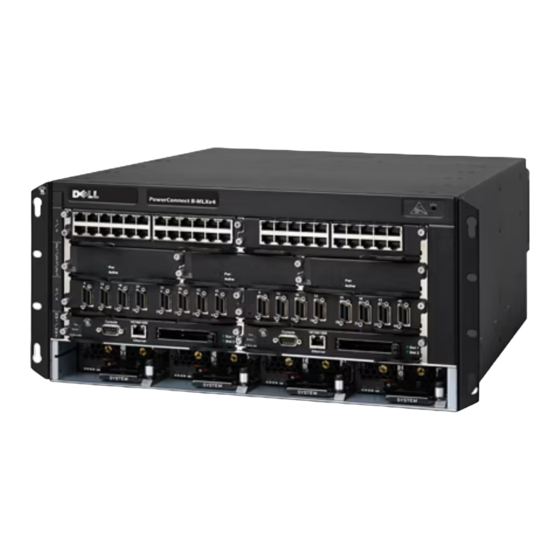
- Seite 7 Figure 2 illustrates the PowerConnect B-MLXe Series 8-slot chassis and components location. FIGURE 2 PowerConnect B-MLXe 8-slot chassis Interface slot 1 Switch fabric slot 2 11 Interface slot 8 16 Power supply slot 3 interface slot 2 Switch fabric slot 3 12 Management slot 1 17 Power supply slot 4 Interface slot 3...
- Seite 8 Figure 3 illustrates the PowerConnect B-MLXe Series 16-slot chassis and components location.and components location. FIGURE 3 PowerConnect B-MLXe 16-slot chassis 1-16 Interface slots 1-16 20 Switch fabric slot 4 Switch fabric slot 1 Management slot 1 Switch fabric slot 2 22 Management slot 2 Switch fabric slot 3 23 ESD connector...
-
Seite 9: Items Required For Installation
Four power supplies (AC or DC). • Warranty card. • A 115V AC power cable for each AC power supply that you purchase from Dell. • Web pointer card containing software images and user documentation (including this guide). NOTE If any items are missing, contact the place of purchase. -
Seite 10: Site Planning And Safety Guidelines
• #2 Phillips-head screwdriver. • A large flat-blade screwdriver. • Mid-mount rack kit (optional). Order from your PowerConnect supplier. • An ESD wrist strap with a plug for connection to the ESD connector on the chassis. Site planning and safety guidelines The following steps and safety precautions are required to ensure correct installation and operation. - Seite 11 CAUTION Do not install the chassis in an environment where the operating ambient temperature might exceed 40 ο C (104 ο F). CAUTION Make sure the air flow around the front, sides, and back of the chassis is not restricted. CAUTION If you do not install a module in a slot, you must keep the slot blank in place.
- Seite 12 DANGER If the installation requires a different power cord than the one supplied with the chassis, make sure you use a power cord displaying the mark of the safety agency that defines the regulations for power cords in your country. The mark is your assurance that the power cord can be used safely with the chassis.
-
Seite 13: Unpacking The Powerconnect B-Mlxe Series
“Mounting a chassis in a rack” Preparing to mount a chassis in a rack Because of the weight of a fully loaded PowerConnect B-MLXe Series chassis, Dell recommends mounting a chassis in a rack before installing modules and AC power supplies if necessary. -
Seite 14: Lifting Guidelines For The 8-Slot And 16-Slot Chassis
For each PowerConnect B-MLXe Series chassis that you install in a rack, you must provide four standard #12-24 pan-head screws with which to mount and secure the chassis. Before performing this task, you should have an assembled rack and a #2 Phillips-head screwdriver. Removing shipping screws from the 4-slot and 8-slot chassis The PowerConnect B-MLXe Series 4-slot and 8-slot units ship with two screws installed in the right side of the chassis. -
Seite 15: Mounting A Chassis In A Rack
Mounting a chassis in a rack Follow these steps to mount a PowerConnect B-MLXe Series chassis in a rack. NOTE You must provide standard #12-24 pan-head screws to mount each chassis in a rack. You will need a Phillips screwdriver to perform this task. 1. -
Seite 16: Installing Modules
FIGURE 6 Mounting the B-MLXe 8-slot chassis in a rack Equipment rack Mounting holes 4. Slide the chassis down so that the mounting screw heads are in the narrow portion of the keyhole slots. 5. Tighten the screws to secure the chassis in place. For extra support, use additional screws. NOTE For better grounding of the chassis to the rack, attach the chassis using star washers. - Seite 17 PowerConnect B-MLXe Series chassis only. For example, if you attempt to install the PowerConnect B-MLXe Series management module in another Dell chassis or a management module intended for another Dell chassis in the PowerConnect B-MLXe Series chassis, the chassis and module will not function properly.
- Seite 18 Before installing a module in the PowerConnect B-MLXe Series chassis, have the following on hand: • An ESD wrist strap with a plug for connection to the ESD connector on the PowerConnect B-MLXe Series chassis. DANGER For safety reasons, the ESD wrist strap should contain a 1 megohm series resistor. •...
- Seite 19 FIGURE 7 Installing a module in 4-slot chassis FIGURE 8 Installing a module in an 8-slot chassis PowerConnect B-MLXe Getting Started Guide 53-1001995-01...
-
Seite 20: Installing Power Supplies
FIGURE 9 Installing a module in a B-MLXe-16 chassis Power supply, switch fabric, and fan requirements For details on power supply, switch fabric, and fan requirements for modules installed in PowerConnect B-MLXe Series units, refer to your hardware installation guide. Installing power supplies Table 2 lists the number of power supplies (AC or DC) installed in the PowerConnect B-MLXe Series at the factory and... - Seite 21 1. Remove the power supply slot blank. CAUTION Empty power supply slots must be covered with slot blanks. 2. Remove the power supply from the packaging. 3. Insert the power supply into the slot, using the guides on each side of the slot. Refer to Figure CAUTION Carefully follow the mechanical guides on each side of the power supply slot and make sure the power...
- Seite 22 FIGURE 11 Installing a power supply in an 8-slot chassis 1 Power supply PowerConnect B-MLXe Getting Started Guide 53-1001995-01...
-
Seite 23: Connecting Ac Power
FIGURE 12 Installing a power supply in a 16-slot chassis Power supply Release latch 6. For information about connecting power to the router, refer to “Connecting AC power” on page 21 or “Connecting DC Power” on page 22. For information about powering on the system, refer to “Activating the power source”... -
Seite 24: Connecting Dc Power
FIGURE 13 Example of connecting a power cord to an AC power supply installed in B-MLXe 4-slot chassis Ground point Power Cord Cord retainer DANGER If the installation requires a different power cord than the one supplied with the chassis, make sure you use a power cord displaying the mark of the safety agency that defines the regulations for power cords in your country. - Seite 25 FIGURE 14 DC power supply for the 8-slot and 16-slot chassis DC IN DC OUT ALM Screws holding plastic cover Screws holding power lugs 2. Use a Phillips head screwdriver to remove each of the power lugs. 3. Crimp #8 AWG power supply wire into the power lugs and reconnect the power lugs to the power supply unit. Refer to Figure CAUTION...
-
Seite 26: Managing Cables
PC or terminal. You can order the serial cable separately from Dell or build your own cable. If you prefer to build your own, see the pinout information in your hardware installation guide. -
Seite 27: Activating The Power Source
If you do not install a module in a slot, you must keep the slot blank in place. If you run the chassis with an uncovered slot, the system may overheat. 2. If your power source is AC, attach one end of a Dell-supplied AC power cord to the AC power supply as described “Connecting AC power”... -
Seite 28: Verifying Proper Operation
3. If you are supplying a DC power source to a PowerConnect B-MLXe Series chassis, attach the power cables to the DC power supply as described in “Connecting DC Power” on page 22. Connect the other end of the cables to the DC power source. Repeat this step for each installed DC power supply. -
Seite 29: Assigning Passwords
Assigning passwords By default, the PowerConnect B-MLXe Series CLI is not protected by passwords. To secure CLI access, Dell strongly recommends assigning passwords. The CLI contains the following access levels: • Privileged EXEC – This level is also called the Enable level and can be secured by a password. From this level you can manage files on the management module flash memory or a PCMCIA flash card in the management module slots 1 or 2, save the system configuration to flash memory, and clear caches. -
Seite 30: Configuring Ip Addresses
Configuring IP addresses The PowerConnect B-MLXe Series implement separate data and control planes. This architecture affects how you assign IP addresses. Table 3 outlines the interfaces to which you can assign IP addresses. In this table, “in band” refers to an interface over which user packets are routed, while “out of band” refers to an interface over which control packets related to system management are forwarded. -
Seite 31: Assigning An Ip Address To An Interface, Virtual Interface, Or Loopback
CAUTION Use the erase startup-config command only for new systems. If you enter this command on a system you have already configured, the command erases the configuration. If you accidentally erase the configuration on a configured system, enter the write memory command to save the running configuration to the startup-config file. -
Seite 32: Connecting The Powerconnect B-Mlxe Series To A Network Device
You can connect a PowerConnect B-MLXe Series chassis to another Ethernet network device. The PowerConnect B-MLXe Series chassis supports connections to other vendors’ as well as Dell network devices. Refer to your hardware installation guide for a description of the Ethernet interface modules available with the PowerConnect B-MLXe Series. -
Seite 33: Regulatory Notices
Regulatory Notices For additional regulatory information, see the Regulatory Compliance Homepage on www.dell.com at the following location: www.dell.com/regulatory_compliance. Información de la NOM (sólo para México) La información que se proporciona a continuación aparece en el dispositivo descrito en este documento, en cumplimiento de los requisitos de la... - Seite 34 PowerConnect B-MLXe Getting Started Guide 53-1001995-01...
- Seite 35 53-1001995-01 53-1001995-01 2010 年 8 月 31 日 PowerConnect™ B-MLXe 系列 入门指南 53-1001995-01 *53-1001995-01*...
- Seite 36 © 2010 Dell Inc. 版权所有,翻印必究。美国印制。 未经 Dell Inc. 书面许可,严禁以任何方式复制这些材料。 本文件中使用的商标: Dell、DELL 徽标、Inspiron、Dell Precision、Dimension、OptiPlex、Latitude、PowerEdge、PowerVault、PowerApp、 PowerConnect 以及 Dell OpenManage 是 Dell Inc. 的商标; Intel、 Pentium 和 Celeron 是 Intel Corporation 在美国和其他国家和地区的注册商 标; Microsoft、Windows、Windows Server、MS-DOS 和 Windows Vista 是 Microsoft Corporation 在美国和 / 或其他国家和地区的商标或注册 商标。...
- Seite 37 • • • • PowerConnect B-MLXe • • • • • • • • • • • • • PowerConnect B-MLXe PowerConnectB-MLXe • • PowerConnect B-MLXe • • (EIA310-D) B-MLXe • (Telco) PowerConnect PowerConnect PowerConnect B-MLXe • (EIA310-D) B-MLXe • (Telco) PowerConnect PowerConnect...
- Seite 38 PowerConnect B-MLXe 图 1 PowerConnect B-MLXe 4 接口插槽 2 ESD 接口 接口插槽 3 接口插槽 4 交换结构插槽 2 接口插槽 1 管理插槽 1 交换结构插槽 3 交换结构插槽 1 管理插槽 2 PowerConnect B-MLXe 入门指南 53-1001995-01...
- Seite 39 PowerConnect B-MLXe 图 2 PowerConnect B-MLXe 8 11 接口插槽 8 16 电源设备插槽 3 接口插槽 1 交换结构插槽 2 12 管理插槽 1 17 电源设备插槽 4 接口插槽 2 交换结构插槽 3 13 管理插槽 2 18 ESD 接口 接口插槽 3 接口插槽 5 14 电源设备插槽 1 接口插槽...
- Seite 40 PowerConnect B-MLXe 图 3 PowerConnect B-MLXe 16 1-16 接口插槽 1-16 20 交换结构插槽 4 交换结构插槽 1 管理插槽 1 22 管理插槽 2 交换结构插槽 2 23 ESD 接口 交换结构插槽 3 PowerConnect B-MLXe 入门指南 53-1001995-01...
- Seite 41 PowerConnect B-MLXe PowerConnect PowerConnect B-MLXe • • • • • Dell 115V • 注 • (EIA310-D) • 12 - 24 • • • PowerConnect • PowerConnect B-MLXe 入门指南 53-1001995-01...
- Seite 42 务 15.24 注 PowerConnect B-MLXe (CBN) (IBN) (OSP) PowerConnect B-MLXe C (104 PowerConnect B-MLXe 入门指南 53-1001995-01...
- Seite 43 PowerConnect B-MLXe 入门指南 53-1001995-01...
- Seite 44 B-MLXe B-MLXe 1800 -48VDC 90 ο C VW-1 NEBS (AWG) PowerConnect B-MLXe 入门指南 53-1001995-01...
- Seite 45 PowerConnect B-MLXe PowerConnect B-MLXe B-MLXe PowerConnect B-MLXe • “ ” • “ ” • “8 ” • “ ” PowerConnect B-MLXe Dell (EIA310-D) • PowerConnect B-MLXe • PowerConnect B-MLXe • PowerConnect B-MLXe PowerConnect B-MLXe 12-24 PowerConnect B-MLXe 入门指南 53-1001995-01...
- Seite 46 PowerConnectB-MLXe 注 图 4 2 后方 前方 运输螺钉 B-MLXe 16 • • • PowerConnect B-MLXe 入门指南 53-1001995-01...
- Seite 47 PowerConnect B-MLXe 注 12-24 2. U 图 5 非对称凸缘设备机架 网络设备机架 PowerConnect B-MLXe 入门指南 53-1001995-01...
- Seite 48 图 6 B-MLXe 8 设备机架 固定孔 注 务 • • (OSP) GR-1089-CORE Issue 4 PowerConnect B-MLXe 入门指南 53-1001995-01...
- Seite 49 注 PowerConnectB-MLXe PowerConnect B-MLXe PowerConnect B-MLXe Dell Dell PowerConnect B-MLXe PowerConnect B-MLXe 表 1 PowerConnect B-MLXe PowerConnect B-MLXe 系列模块 机箱插槽号 适用于 4 插槽和 8 插槽机箱的管理模块 活动模块 – M1 (左) 冗余模块 – M2 (右) 活动模块 – M1 (上) 适用于 16 插槽机箱的管理模块...
- Seite 50 PowerConnect B-MLXe show running-config PowerConnect(config)# show running-config Current configuration: ver V5.0.0T163 module 1 ni-mlx-24-port-1g-copper 1 Gbps show running-config no module <slot-number> <module-type> PowerConnect(config)# no module 1 ni-mlx-20-port-1g-copper 注 write memory PowerConnect(config)# write memory Write startup-config done. PowerConnect B-MLXe 入门指南 53-1001995-01...
- Seite 51 图 7 图 8 PowerConnect B-MLXe 入门指南 53-1001995-01...
- Seite 52 图 9 B-MLXe-16 PowerConnect B-MLXe PowerConnect B-MLXe 表 2 B-MLXe 机箱类型 已安装电源 最大电源设 设备 备数 4 插槽 8 插槽 16 插槽 PowerConnect B-MLXe 入门指南 53-1001995-01...
- Seite 53 步骤 闲置 须 沿 边 械 轨 操 正 轨 倒着 图 10 PowerConnect B-MLXe 入门指南 53-1001995-01...
- Seite 54 图 11 1 电源设备 PowerConnect B-MLXe 入门指南 53-1001995-01...
- Seite 55 图 12 电源设备 释放闩锁 步骤 B-MLXe PowerConnect B-MLXe 入门指南 53-1001995-01...
- Seite 56 图 13 例: B-MLXe 4 接地点 电源线 线缆定位器 PowerConnect B-MLXe DC-DC DC-DC /100 PowerConnect B-MLXe 入门指南 53-1001995-01...
- Seite 57 图 14 DC IN DC OUT ALM 用于固定塑料盖板的螺钉 用于固定电源接线片的螺钉 #8 AWG 符 PowerConnect B-MLXe NEBS 此 关 附 则 须 头 任 洁 图 15 #8 AWG 电源设备线 -48V 注 (DC-I) NEC/CEC PowerConnect B-MLXe 入门指南 53-1001995-01...
- Seite 58 10/100 DB-9 10BaseT/100Base TX RJ-45 UTP PowerConnect B-MLXe PowerConnect B-MLXe • • EIA/TIA DB-9 DB-9 DB-9 DB-25 Dell • • Baud: 9600 bps • Data bits: 8 • Parity: None • Stop bits: 1 • Flow control: None PowerConnect B-MLXe 入门指南...
- Seite 59 10BaseT/100BaseTX/1000BaseTX RJ-45 UTP PowerConnect B-MLXe Dell 则 须 遮 Dell 115V 120V 注 务 PowerConnect B-MLXe 注 PowerConnect B-MLXe PowerConnect B-MLXe PowerConnect B-MLXe 入门指南 53-1001995-01...
- Seite 60 PowerConnect B-MLXe • • PowerConnect B-MLXe CLI show module 门 PowerConnect B-MLXe 窗 Enter PowerConnect> 看 牢 查 看 目 (PowerConnect>) 层级 PowerConnect# show module Module Status Ports Starting MAC M1 (upper): NI-MLX-MR Mgmt Module Active M2 (lower): F0: NI-MLX-MR Switch Fabric Module Active S4: NetIron 4-Port 10Gig Module CARD_STATE_UP...
- Seite 61 默 情况 护 护 CLI Dell 强烈 PowerConnect B-MLXe 级 • 级 亦称 启 级 护 级 Privileged EXEC – 快擦写 储 PCMCIA 闪 快擦写 储 清 缓 • 级 级 CONFIG – CONFIG EXEC Privileged 级 启 级 •...
- Seite 62 实 体 影响 概 PowerConnect B-MLXe (in band) (out of band) 传 表 3 址 接口 相关物理端口 带外或带内 管理接口 已激活或冗余管理模块上的以太网 带外 10/100/1000 端口 用户信息包所路由通过的任一接口 任一接口模块端口 带内 用户信息包所路由通过的任一虚拟接口 任一接口端口 带内 – 回送接口 带内 就 • 掩 PowerConnect B-MLXe • • 虚 掩...
- Seite 63 新 erase startup-config 命令 您 置 此命令 您 置 被擦 意外 擦 置信息 写 存储 命令 置 存 启 置文 级 PowerConnect# configure terminal Privileged EXEC Level PowerConnect(config)# Global CONFIG Level 掩 PowerConnect(config)# interface management 1 PowerConnect(config-if-mgmt-1)# ip address 10.0.1.1 255.255.255.0 虚...
- Seite 64 La información que se proporciona a continuación aparece en el dispositivo descrito en este documento, en cumplimiento de los requisitos de la Norma Oficial Mexican (NOM): Importador: Dell Inc. de México, S.A. de C.V. Paseo de la Reforma 2620-11 Piso Col.
- Seite 65 53-1001995-01 2010 PowerConnect™ B-MLXe 53-1001995-01 *53-1001995-01*...
- Seite 66 © 2010 Dell Inc. 未經 Dell Inc. 的書面許可,不得以任何形式進行複製。 本文件中使用的商標: Dell、DELL 徽標、Inspiron、Dell Precision、Dimension、OptiPlex、Latitude、PowerEdge、PowerVault、PowerApp、 PowerConnect 與 Dell OpenManage 是 Dell Inc. 的商標;Intel、Pentium 和 Celeron 是 Intel Corporation 在美國和其他國家的的註冊商標; Microsoft、Windows、 Windows Server、 MS-DOS 與 Windows Vista 是 Microsoft Corporation 在美國和╱或其他國家的商標或註冊商標。 本文件中使用的其它商標與商品名稱是指擁有這些標誌及名稱的公司或其產品。 Dell Inc. 對於不屬於其本身的商品與名稱將不擁有任何專有...
- Seite 67 • • • • • PowerConnect B-MLXe • PowerConnect B-MLXe • • • • • • • • • • • PowerConnect B-MLXe PowerConnect B-MLXe • • PowerConnect B-MLXe • • (EIA310-D) B-MLXe • (Telco) PowerConnect PowerConnect PowerConnect B-MLXe • (EIA310-D) B-MLXe •...
- Seite 68 PowerConnect B-MLXe PowerConnect B-MLXe 圖 1 PowerConnect B-MLXe 4 介面插槽 2 ESD 連接器 介面插槽 3 介面插槽 4 交換核心插槽 2 介面插槽 1 管理插槽 1 交換核心插槽 3 交換核心插槽 1 管理插槽 2 PowerConnect B-MLXe 使用說明指南 53-1001995-01...
- Seite 69 PowerConnect B-MLXe 圖 2 PowerConnect B-MLXe 8 11 介面插槽 8 16 電流供應器插槽 3 介面卡插槽 1 交換核心插槽 2 12 管理插槽 1 17 電源供應器插槽 4 介面插槽 2 交換核心插槽 3 13 管理插槽 2 18 ESD 連接器 介面插槽 3 介面插槽 5 14 電源供應器插槽 1 介面插槽...
- Seite 70 PowerConnectB-MLXe 圖 3 PowerConnect B-MLXe 16 1-16 介面插槽 1-16 20 交換核心插槽 4 交換核心插槽 1 管理插槽 1 22 管理插槽 2 交換核心插槽 2 23 ESD 連接器 交換核心插槽 3 PowerConnect B-MLXe 使用說明指南 53-1001995-01...
- Seite 71 PowerConnect B-MLXe PowerConnect PowerConnect B-MLXe • (slot blank) • • • • 115V Dell • Web Pointer Card 註 • (EIA310-D) • #12-24 • • • PowerConnect • PowerConnect B-MLXe 使用說明指南 53-1001995-01...
- Seite 72 壁 15.24 註 PowerConnect B-MLXe (Common Bonding Network CBN) (Isolated Bonding Network IBN) (Outside Plant installations OSP) PowerConnect B-MLXe 危險 危險 警示 40 C (104 F) 警示 PowerConnect B-MLXe 使用說明指南 53-1001995-01...
- Seite 73 警示 警示 警示 危險 危險 危險 危險 危險 PowerConnect B-MLXe 使用說明指南 53-1001995-01...
- Seite 74 危險 警示 (amp) 警示 B-MLXe 警示 B-MLXe 警示 1800W) (input lug) UL-Listed 60 amp -48VDC 6 AWG VW-1 90 C 警示 NEBS (AWG) PowerConnect B-MLXe PowerConnect B-MLXe B-MLXe PowerConnect B-MLXe 使用說明指南 53-1001995-01...
- Seite 75 PowerConnect B-MLXe • • • • PowerConnect B-MLXe Dell (EIA310-D) • PowerConnect B-MLXe • PowerConnect B-MLXe • PowerConnect B-MLXe PowerConnect B-MLXe #12-24 PowerConnect B-MLXe 註 圖 4 2 背面 正面 運輸螺絲 PowerConnect B-MLXe 使用說明指南 53-1001995-01...
- Seite 76 危險 B-MLXe 16 • • • PowerConnect B-MLXe 註 #12-24 2. U 圖 5 不等邊法蘭設備機架 網路設備機架 (Unequal flange equipment rack) PowerConnect B-MLXe 使用說明指南 53-1001995-01...
- Seite 77 圖 6 B-MLXe 8 設備機架 裝設孔 註 • • 危險 (OSP) GR-1089-CORE Issue 4 (Primary Protector) PowerConnect B-MLXe 使用說明指南 53-1001995-01...
- Seite 78 註 PowerConnect B-MLXe PowerConnect B-MLXe PowerConnect B-MLXe Dell Dell PowerConnect B-MLXe PowerConnect B-MLXe 表 1 PowerConnect B-MLXe PowerConnect B-MLXe 系列模組 機箱插槽編號 4 插槽和 8 插槽機箱的管理模組 使用中模組 – M1 ( 左 ) 備援模組 – M2 ( 右 ) 16 插槽機箱的管理模組 使用中模組 – M1 ( 上 ) 備援模組...
- Seite 79 PowerConnect B-MLXe show running-config PowerConnect(config)# show running-config 目前配置: 版本 V5.0.0T163 模組 1 ni-mlx-24-port-1g-copper 20-port 1 Gbps (copper interface) show running-config no module <slot-number> <module-type> PowerConnect(config)# no module 1 ni-mlx-20-port-1g-copper 註 write memory PowerConnect(config)# write memory 寫入 startup-config 已完成。 圖 7 PowerConnect B-MLXe 使用說明指南...
- Seite 80 圖 8 圖 9 B-MLXe-16 PowerConnect B-MLXe PowerConnect B-MLXe 使用說明指南 53-1001995-01...
- Seite 81 PowerConnect B-MLXe 表 2 B-MLXe 機箱類型 已安裝的電 電源供應器 源供應器 上限 4 插槽 8 插槽 16 插槽 危險 步驟 警示 空 警示 仔細依循 邊 械 軌 軌 意 向 正 PowerConnect B-MLXe 使用說明指南 53-1001995-01...
- Seite 82 圖 10 圖 11 1 電源供應器 PowerConnect B-MLXe 使用說明指南 53-1001995-01...
- Seite 83 圖 12 電源供應器 釋放閂 步驟 B-MLXe (cord retainer) PowerConnect B-MLXe 使用說明指南 53-1001995-01...
- Seite 84 圖 13 B-MLXe 4 範例 接地點 電源線 托線器 危險 PowerConnect B-MLXe 48 V 30 A 12 V 100 A 危險 PowerConnect B-MLXe 使用說明指南 53-1001995-01...
- Seite 85 圖 14 DC IN DC OUT ALM 固定塑膠蓋的螺絲 固定電源供應器突耳的螺絲 #8 AWG 警示 NEBS PowerConnect B-MLXe (AWG) 圖 15 #8 AWG 的電源供應器電線 -48V 註 (DC return) (DC-I) NEC/CEC PowerConnect B-MLXe 使用說明指南 53-1001995-01...
- Seite 86 10BaseT/100BaseTX/1000BaseTX Telnet 10BaseT/100BaseTX/1000BaseTX • PowerConnect B-MLXe 10BaseT/100BaseTX/1000BaseTX 註 10/100 DB-9 10BaseT/100Base TX RJ-45 UTP PowerConnect B-MLXe Telnet PowerConnect B-MLXe Telnet • • EIA/TIA DB-9 DB-9 DB-9 DB-25 Dell • • 9600 bps • • • • PowerConnect B-MLXe 使用說明指南 53-1001995-01...
- Seite 87 10BaseT/100BaseTX/1000BaseTX (RJ-45 UTP PowerConnect B-MLXe (Dell 警示 Dell 壁 115V 120V 危險 註 PowerConnect B-MLXe 註 壁 PowerConnect B-MLXe PowerConnect B-MLXe PowerConnect B-MLXe 使用說明指南 53-1001995-01...
- Seite 88 S4: NetIron 4 連接埠 10Gig 模組 CARD_STATE_UP 000c.db80.0000 S5: NetIron 4 連接埠 10Gig 模組 CARD_STATE_UP 000c.db80.0000 S6: NetIron 4 連接埠 10Gig 模組 CARD_STATE_UP 000c.db80.0000 況 護 護 CLI Dell 強烈 PowerConnect B-MLXe 層級 • 權限 EXEC – 層級 稱 層級 護 層級 掌握 快閃記憶 檔案...
- Seite 89 層級 • – 擁 寫權限 員 唯 層級 註 • 寫 寫 – • 唯 權限 EXEC – CONFIG 變 權限層級 EXEC PowerConnect> enable PowerConnect# CONFIG 層級 PowerConnect# configure terminal PowerConnect(config)# PowerConnect(config)# enable super-user-password <text> 註 唯 PowerConnect(config)# enable port-config-password <text> PowerConnect(config)# enable read-only-password <text>...
- Seite 90 • 遮罩 PowerConnect B-MLXe • • 虛 遮罩 (A B C 遮罩 別 域 擇 (CIDR) PowerConnect B-MLXe 遮罩 • 遮罩 遮罩 209.157.22.99 255.255.255.0 遮罩 • 遮罩 遮罩 斜 擁 遮罩 遮罩 209.157.22.99/24 B-MLXe 變 10.0.1.1 enable PowerConnect> enable 權限 EXEC 層級 消...
- Seite 91 虛 測 診 Telnet 況 虛 遮罩 255.255.255.0 192.22.3.44 enable PowerConnect> enable 權限 EXEC 層級 消 測 Enter PowerConnect# erase startup-config 警示 新 令 果 令 令就 消除原 erase startup-config 慎消除 寫 記憶 令 執 儲存 startup-config 檔案 層級 PowerConnect# configure terminal PowerConnect(config)# 遮罩...
- Seite 92 La información que se proporciona a continuación aparece en el dispositivo descrito en este documento, en cumplimiento de los requisitos de la Norma Oficial Mexican (NOM): Importador: Dell Inc. de México, S.A. de C.V. Paseo de la Reforma 2620-11°Piso Col. Lomas Altas 11950 México, D.F.
- Seite 93 53-1001995-01 31 Août 2010 PowerConnect™ Série B-MLXe Guide de mise en route 53-1001995-01 *53-1001995-01*...
- Seite 94 D'autres marques et noms commerciaux peuvent être utilisés dans ce document pour faire référence aux entités se réclamant de ces marques ou noms ou à leurs produits. Dell Inc. rejette tout intérêt exclusif dans les marques et les noms commerciaux autres que les siens.
-
Seite 95: Présentation
Dans ce guide • Présentation ............. . 93 •... - Seite 96 Le châssis PowerConnect de série B-MLXe à 16 logements (Figure 48 à la page 96) peut être installé des manières suivantes : • Dans une armoire de 19 pouces Electronic Industries Association (EIA310-D). Les unités de série B-MLXe comportent des supports de montage intégrés pour l'installation en rack. •...
- Seite 97 Figure 47 illustre le châssis PowerConnect de série B-MLXe à 8 logements et l'emplacement des composants. FIGURE 47 Châssis PowerConnect B-MLXe à 8 logements Logement d'interface 1 Logement de matrice de 11 Logement d'interface 8 16 Logement de bloc commutation 2 d'alimentation 3 Logement d'interface 2 Logement de matrice de...
- Seite 98 Figure 48 illustre le châssis PowerConnect de série B-MLXe à 16 logements et l'emplacement des composants. FIGURE 48 PowerConnect B-MLXe châssis à 16 logements 1-16 Logements d'interface 1 à 16 20 Logement de matrice de commutation 4 Logement de matrice de commutation 1 Logement de gestion 1 Logement de matrice de commutation 2 22 Logement de gestion 2...
-
Seite 99: Éléments Nécessaires À L'installation
La carte de garantie. • Un câble d'alimentation secteur 115 V pour chaque bloc d'alimentation secteur que vous achetez auprès de Dell. • Une carte de redirection Web contenant des images de logiciel et la documentation utilisateur (notamment ce guide). -
Seite 100: Planification De Site Et Consignes De Sécurité
Éléments que vous devez fournir • Rack d'équipement d'armoire de 19 pouces Electronic Industries Association (EIA310-D) assemblé. • Vis à tête cylindrique no. 12 à 24 standard pour le montage du châssis sur les racks d'équipement. • Tournevis cruciforme no. 2. •... -
Seite 101: Précautions Générales
Précautions générales AVERTISSEMENT Les procédures de ce manuel ne devraient être effectuées que un personnel de maintenance qualifié. AVERTISSEMENT Toutes les interfaces à fibre optique utilisent des lasers de classe 1. PRÉCAUTION N'installez pas le châssis dans un environnement où la température ambiante de fonctionnement pourrait dépasser 40 °C (104 °F). - Seite 102 AVERTISSEMENT Déconnectez le cordon d'alimentation de toutes les sources d'alimentation pour totalement couper l'alimentation du châssis. AVERTISSEMENT Assurez-vous que les circuits de source d'alimentation sont correctement mis à la terre, puis utilisez le cordon d'alimentation fourni avec le châssis pour le connecter à la source d'alimentation.
-
Seite 103: Déballage Du Châssis Powerconnect De Série B-Mlxe
PRÉCAUTION Les produits de série B-MLXe avec source d'alimentation en CC sont conçus pour une installation uniquement dans des zones d'accès restreint. Une zone d'accès restreint est un endroit auquel seul peut accéder un personnel de maintenance utilisant un outil, un verrou et une clé... - Seite 104 Préparation du montage d'un châssis dans un rack En raison du poids d'un châssis PowerConnect de série B-MLXe complètement chargé, Dell vous recommande de monter le châssis dans un rack avant d'installer des modules et blocs d'alimentation secteur, le cas échéant.
-
Seite 105: Consignes De Soulèvement Des Châssis À 4 Logements Et À 8 Logements
Consignes de soulèvement des châssis à 4 logements et à 8 logements AVERTISSEMENT Un châssis B-MLXe à 16 logements complètement chargé est lourd. IL FAUT DEUX PERSONNES POUR SOULEVER, MANIPULER OU MONTER CES APPAREILS. Respectez les consignes suivantes lorsque vous soulevez et déplacez les châssis à 8 logements ou à 16 logements : •... - Seite 106 3. En commençant par le châssis que vous souhaitez monter dans la position la plus basse du rack, montez le châssis dans le rack comme illustré dans l'exemple du châssis à 8 logements à la Figure 51. Alors qu'au moins deux personnes soulèvent le châssis, glissez la partie large de chaque logement en trou de serrure au-dessus de la vis de montage correspondante dans le support vertical de rack.
-
Seite 107: Installation De Modules
PowerConnect de série B-MLXe. Par exemple, si vous tentez d'installer le module de gestion PowerConnect de série B-MLXe dans un autre châssis Dell ou dans un module de gestion conçu pour un autre châssis Dell dans le châssis PowerConnect de série B-MLXe, le châssis et le module ne fonctionneront pas correctement. - Seite 108 PRÉCAUTION Si vous utilisez un tournevis électrique, vous risquez de tordre les têtes des vis ; une telle utilisation n'est donc pas recommandée. PRÉCAUTION Si vous n'installez pas de module dans un logement, vous devez garder le cache à sa place. Si vous faites fonctionner le châssis alors qu'un logement n'est pas couvert, il se peut que le système surchauffe.
- Seite 109 b. Avec la désignation de module de la sortie de commande show running-config (afficher la configuration en cours), utilisez la commande no module <slot-number> <module-type> (aucun module - numéro de logement - type de module) pour effacer la configuration du logement 1. PowerConnect(config)# no module 1 ni-mlx-20-port-1g-copper Cette commande efface la configuration du logement 1, le laissant prêt à...
- Seite 110 FIGURE 53 Installation d'un module dans un châssis à 8 logements FIGURE 54 Installation d'un module dans un châssis B-MLXe -16 Guide de mise en route PowerConnect B-MLXe 53-1001995-01...
-
Seite 111: Installation Des Blocs D'alimentation
Exigences de bloc d'alimentation, matrice de commutation, et ventilateur Pour en savoir plus sur les exigences de bloc d'alimentation, les matrices de commutation et les ventilateurs des modules installés dans les unités PowerConnect de série B-MLXe, reportez-vous à votre guide d'installation du matériel. - Seite 112 4. Dans le cas des châssis à 4 logements, suivez ces étapes, puis passez à l'étape a. Poussez le panneau avant du bloc d'alimentation dans le routeur jusqu'à ce qu'il s'engage dans le connecteur de fond de panier. b. Tournez les leviers d'éjection vers l'avant du bloc d'alimentation pour le fixer en place. Serrez les deux vis situées sur le panneau avant du bloc d'alimentation en appuyant dessus et en les tournant dans le sens des aiguilles d'une montre.
- Seite 113 FIGURE 56 Installation d'un bloc d'alimentation dans un châssis à 8 logements 1 Bloc d'alimentation Guide de mise en route PowerConnect B-MLXe 53-1001995-01...
-
Seite 114: Connexion De L'alimentation Secteur
FIGURE 57 Installation d'un bloc d'alimentation dans un châssis à 16 logements Bloc d'alimentation Loquet 6. Pour davantage d'informations concernant la connexion de l'alimentation au routeur, voir « Connexion de l'alimentation secteur » à la page 112 ou « Connexion de l'alimentation en CC » à... -
Seite 115: Connexion De L'alimentation En Cc
FIGURE 58 Exemple de connexion d'un cordon d'alimentation à un bloc d'alimentation secteur installé dans un B-MLXechâssis à 4 logements Point de mise à la terre 2 Cordon d'alimentation 3 Dispositif de fixation des câbles AVERTISSEMENT Si l'installation exige un cordon d'alimentation autre que celui fourni avec le châssis, assurez-vous d'utiliser un cordon d'alimentation portant la marque de l'agence de sécurité... - Seite 116 FIGURE 59 Bloc d'alimentation en CC pour les châssis à 8 et à 16 logements DC IN DC OUT ALM Vis maintenant en place le cache en plastique Vis maintenant en place les cosses d'alimentation 2. Utilisez un tournevis cruciforme pour retirer chacune des cosses d'alimentation. 3.
-
Seite 117: Gestion Des Câbles
PC ou terminal. Vous pouvez commander le câble série indépendamment de Dell ou bien construire votre propre câble. Si vous choisissez de le construire vous-même, reportez-vous aux informations de brochage qui figurent dans votre guide d'installation du matériel. -
Seite 118: Activation De La Source D'alimentation
Pour connecter le port Ethernet du module de gestion à un réseau, vous aurez besoin d'un câble intermédiaire UTP de catégorie 5 (non fourni par Dell). Connectez une extrémité du câble intermédiaire au port de gestion et l'autre extrémité au réseau. -
Seite 119: Vérification Du Bon Fonctionnement
REMARQUE Le châssis PowerConnect de série B-MLXe est conçu pour fournir un service non interrompu même lorsque vous insérez ou retirez les modules de gestion et les modules d'interface. Ainsi, le système ne comporte pas d'interrupteur act./dés. distinct. Pour mettre hors tension le système, débranchez tout simplement les cordons d'alimentation. -
Seite 120: Attribution De Mots De Passe
Attribution de mots de passe Par défaut, l'interface CLI du PowerConnect de série B-MLXe n'est pas protégée par des mots de passe. Pour sécuriser l'accès CLI, Dell recommande vivement d'attribuer des mots de passe. L'interface CLI contient les niveaux d'accès suivants : •... -
Seite 121: Configuration D'adresses Ip
3. Saisissez la commande suivante pour définir le mot de passe superutilisateur : PowerConnect(config)# enable super-user-password <text> REMARQUE Vous devez définir le mot de passe superutilisateur avant de définir d'autres types de mot de passe. 4. Saisissez les commandes suivantes pour définir la configuration du port et les mots de passe lecture seule : PowerConnect(config)# enable port-config-password <text>... - Seite 122 Prise en charge des masques de sous-réseau La série PowerConnect B-MLXe prend en charge les masques de réseau IP classiques (masques de sous-réseau de classe A, B, et C, etc.) et les masques préfixes de réseau CIDR (Classless Interdomain Routing - Routage inter-domaine sans classes).
- Seite 123 Attribution d'une adresse IP à une interface, une interface virtuelle ou une boucle de rappel Vous devez attribuer une adresse IP à chaque interface et interface virtuelle sur laquelle sont acheminés des paquets utilisateur. Vous pouvez aussi attribuer une adresse IP à une interface de boucle de rappel, qui est généralement utilisée à...
-
Seite 124: Connexion Du Châssis Powerconnect De Série B-Mlxe À Un Périphérique Réseau
Réglementations Pour des informations supplémentaires sur les réglementations, reportez-vous à la page d'accueil relative à celles-ci sur www.dell.com à l'adresse suivante : www.dell.com/regulatory_compliance. Información de la NOM (sólo para México) La información que se proporciona a continuación aparece en el dispositivo descrito en este documento, en cumplimiento de los requisitos de la... - Seite 125 53-1001995-01 August 31, 2010 PowerConnect™ B-MLXe-Reihe Handbuch zum Einstieg 53-1001995-01 *53-1001995-01*...
- Seite 126 Andere Marken und Markennamen, die in diesem Dokument vorkommen, beziehen sich entweder auf die juristischen Personen, die diese Marken und Namen beanspruchen, oder auf ihre Produkte. Dell Inc. lehnt jegliche Besitzrechte an den Marken und Markennamen außer ihren eigenen ab.
-
Seite 127: In Diesem Handbuch
In diesem Handbuch • Einführung ........... . 125 •... - Seite 128 • In ein Mid-mount Telekommunikations- (Telco) Rack. Ein Mid-mount-Einbausatz kann von Ihrem PowerConnect-Anbieter getrennt bestellt werden, um die PowerConnect-Einheit zentriert montiert in das Rack einzubauen. Es enthält zwei L-förmige Montagebleche und Anweisungen zum Installieren der Bleche und für die Montage des Gerätes. In diesem Handbuch werden die grundlegenden Konfigurationsschritte aufgeführt, die zur Einrichtung von Geräten der PowerConnect B-MLXe-Reihe erforderlich sind.
- Seite 129 Abbildung 62 veranschaulicht das Gehäuse der PowerConnect B-MLXe-Reihe mit 8 Einschüben und die Anordnung der Komponenten. ABBILDUNG 62 PowerConnect B-MLXe Gehäuse mit 8 Einschüben Schnittstelleneinschub 1 Switch-Architektur Einschub 2 11 Schnittstelleneinschub 8 16 Netzteileinschub 3 Schnittstelleneinschub 2 Switch-Architektur Einschub 3 12 Verwaltungseinschub 1 17 Netzteileinschub 4 Schnittstelleneinschub 3...
- Seite 130 Abbildung 63 veranschaulicht das Gehäuse der PowerConnect B-MLXe-Reihe mit 16 Einschüben und die Anordnung der Komponenten. ABBILDUNG 63 PowerConnect B-MLXe Gehäuse mit 16 Einschüben 1-16 Schnittstelleneinschübe 1-16 20 Switch-Architektureinschub 4 Switch-Architektur Einschub 1 Verwaltungseinschub 1 Switch-Architektur Einschub 2 22 Verwaltungseinschub 2 Switch-Architektur Einschub 3 23 ESD-Stecker PowerConnect B-MLXe Handbuch zum Einstieg...
-
Seite 131: Für Die Installation Wird Benötigt
Informationen über Lüfter auf Ihr Hardwareinstallationshandbuch. Vier Netzteile (Wechsel- oder Gleichstrom). • Garantiekarte. • Ein 115V Netzkabel für jedes bei Dell gekaufte Netzteil. • Web-Hinweiskarte mit Software-Abbildern und Benutzerdokumentation (einschließlich dieses Handbuchs). ANMERKUNGEN Kontaktieren Sie bei Fehlen jeglicher Gegenstände die Verkaufsstelle. -
Seite 132: Gegenstände, Die Sie Bereitstellen Müssen
Gegenstände, die Sie bereitstellen müssen • Montierter 19-Zoll Electronic Industries Association Geräte-Rack (Schrank) (EIA310-D). • Standard #12-24 Flachkopfschraube zur Montage des Gehäuses in Geräte-Racks. • #2 Kreuzschlitzschraubenzieher. • Ein großer Schlitzschraubenzieher. • Mid-mount Rack-Einbausatz (optional). Bestellen Sie bei Ihrem PowerConnect-Anbieter. •... -
Seite 133: Sicherheitshinweise
Sicherheitshinweise Lesen Sie die auf die PowerConnect B-MLXe-Reihe zutreffenden Vorsichtshinweise und Warnungen, bevor Sie mit der Installation fortfahren. Allgemeine Sicherheitsvorkehrungen WARNUNGEN Die Anweisungen in diesem Handbuch richten sich an qualifiziertes Servicepersonal. WARNUNGEN Alle Glasfaserschnittstellen verwenden Laser der Klasse 1. VORSICHTSHINWEIS Installieren Sie das Gehäuse nicht in einer Umgebung, in der die Betriebsumgebungstemperatur möglicherweise 40°C übersteigt. -
Seite 134: Vorsichtsmaßnahmen Hinsichtlich Der Stromversorgung
Vorsichtsmaßnahmen hinsichtlich der Stromversorgung VORSICHTSHINWEIS Verwenden Sie aus Redundanzgründen für jedes Stromkabel ein getrenntes Netzkabel, für den Fall, dass einer der Stromkreise ausfällt. WARNUNGEN Stellen Sie sicher, dass Sie je nach Anzahl der im Gerät installierten Stromversorgungen die richtige Schaltungsanordnung wählen. WARNUNGEN Trennen Sie das Netzkabel von allen Energiequellen, um das Gehäuse vollständig vom Strom zu nehmen. - Seite 135 VORSICHTSHINWEIS Stellen Sie sicher, dass das Gehäuse nicht die Stromkreise, Verkabelung und den Überspannungsschutz überlädt. Addieren Sie die Belastbarkeit in Ampere (Amp) aller Geräte, die auf demselben Schaltkreis wie das Gehäuse installiert sind, um die Wahrscheinlichkeit für eine Überladung der Stromversorgungskreisläufe zu bestimmen. Vergleichen Sie diese Summe mit der Belastbarkeitsgrenze des Schaltkreises.
-
Seite 136: Auspacken Des Powerconnect B-Mlxe-Reihe
„Rackmontage eines Gehäuses“ Vorbereitung auf die Rackmontage eines Gehäuses Aufgrund des Gewichtes eines voll beladenen Gerätes der PowerConnect B-MLXe-Reihe empfiehlt Dell, das Gehäuse vor der Installation von Modulen und Netzteilen in ein Rack zu montieren, falls erforderlich. In ein Standard-19-Zoll (EIA310-D) Rack können Sie folgendes installieren •... -
Seite 137: Entfernen Der Transportschrauben Von Gehäusen Mit 4 Und 8 Einschüben
Entfernen der Transportschrauben von Gehäusen mit 4 und 8 Einschüben Die Geräte der PowerConnectB-MLXe-Reihe mit 4 Einschüben und 8 Einschüben werden mit zwei Schrauben verschickt, die in der rechten Gehäuseseite installiert sind. Diese Schrauben sichern das Lüfter-Auflagefach und schützen es während des Versands vor Beschädigungen. Sie müssen diese Schrauben vor der Installation des Routers entfernen. -
Seite 138: Rackmontage Eines Gehäuses
Rackmontage eines Gehäuses Befolgen Sie diese Schritte, um ein Gehäuse der PowerConnect B-MLXe-Reihe in ein Rack zu installieren. ANMERKUNGEN Sie müssen zur Montage aller Gehäuse in ein Rack Standard Flachkopfschrauben Nr. 12-24 bereitstellen. Zum Durchführen dieser Aufgabe benötigen Sie einen Kreuzschlitzschraubenzieher. 1. -
Seite 139: Installieren Von Modulen
ABBILDUNG 66 Montage des B-MLXe Gehäuses mit 8 Einschüben in ein Rack Geräte-Rack Montagelöcher 4. Schieben Sie das Gehäuse herunter, sodass sich die Montageschraubenköpfe im engen Teil der Schlüssellochöffnungen befinden. 5. Ziehen Sie die Schrauben an, um die Position des Gehäuses zu sichern. Verwenden Sie weitere Schrauben für zusätzlichen Halt. - Seite 140 Die Module der PowerConnect B-MLXe-Reihe sind dediziert, was bedeutet, dass Sie sie ausschließlich in Gehäusen der PowerConnect B-MLXe-Reihe installieren dürfen. Wenn Sie z.B. das Verwaltungsmodul der PowerConnect B-MLXe-Reihe in ein anderes Dell-Gehäuse oder ein für ein weiteres Dell-Gehäuse der PowerConnect-Reihe gedachtes Verwaltungsmodul zu installieren versuchen, B-MLXe werden das Gehäuse und Modul nicht ordnungsgemäß...
- Seite 141 VORSICHTSHINWEIS Die Verwendung eines Motorschraubendrehers kann die Köpfe der Schrauben abdrehen und wird nicht empfohlen. VORSICHTSHINWEIS Wenn Sie in einem Einschub kein Modul installieren, müssen Sie die Einschubblende installiert lassen. Wenn Sie das Gehäuse mit einem freigelegten Einschub betreiben, überhitzt sich das System möglicherweise. Ziehen Sie die Schrauben an, die die Einschubblenden sichern, sodass diese in Position bleiben, wenn anliegende Blenden oder Module entfernt werden.
- Seite 142 Befolgen Sie die untenstehenden Schritte, um ein Modul in ein Gehäuse der PowerConnect B-MLXe-Reihe zu installieren: 1. Wenn Sie ein Modul in einen leeren Einschub installieren, der zuvor nicht für ein anderes Modul konfiguriert wurde, dann fahren Sie fort mit Schritt 2.
- Seite 143 ABBILDUNG 67 Installieren eines Moduls in ein Gehäuse mit 4 Einschüben ABBILDUNG 68 Installieren eines Moduls in ein Gehäuse mit 8 Einschüben PowerConnect B-MLXe Handbuch zum Einstieg 53-1001995-01...
-
Seite 144: Netzteil, Switch-Architektur Und Lüfteranforderungen
ABBILDUNG 69 Installieren eines Moduls in ein Gehäuse mit B-MLXe 16 Einschüben Netzteil, Switch-Architektur und Lüfteranforderungen Beziehen Sie sich für Einzelheiten zu Netzteil, Switch-Architektur und Lüfteranforderungen für in Geräten der PowerConnect B-MLXe-Reihe installierte Module auf Ihr Hardwareinstallationshandbuch. Installieren von Netzteilen Tabelle 8 führt die Anzahl der von Werk ab in der PowerConnect B-MLXe-Reihe installierten Netzteile (Wechsel- bzw. - Seite 145 Schritte für die Netzteilinstallation Befolgen Sie diese Schritte, um ein Netzteil zu installieren. Sie benötigen zum Durchführen dieser Aufgabe einen kleinen Kreuzschlitz- oder Flachkopfschraubendreher. 1. Entfernen Sie die Einschubblende des Netzteils. VORSICHTSHINWEIS Leere Netzteileinschübe müssen mit Einschubblenden abgedeckt werden. 2. Nehmen Sie das Netzteil aus der Verpackung. 3.
- Seite 146 5. Befolgen Sie für die Gehäuse mit 4 und 16 Einschüben diese Schritte und fahren Sie anschließend fort mit Schritt a. Schieben Sie die Karte entlang der Kartenführung, bis sie vollständig eingesetzt ist und drücken Sie anschließend die Netzteil-Frontblende in Richtung der Gehäuserückeite. Durch diese Aktion rastet der Netzteilstecker in den Anschluss auf der Rückwandplatine ein.
-
Seite 147: Anschließen Des Netzstroms
ABBILDUNG 72 Netzteilinstallation in einem Gehäuse mit 16 Einschüben Netzteil Freigabevorrichtung 6. Beziehen Sie sich für Informationen über den Stromanschluss des Routers auf „Anschließen des Netzstroms“ auf Seite 145 oder „Anschließen des Netzstroms“ auf Seite 146. Beziehen Sie sich für Informationen über das Einschalten des Systems auf „Aktivieren der Energiequelle“... -
Seite 148: Anschließen Des Netzstroms
ABBILDUNG 73 Beispiel für das Anschließen eines Netzkabels an ein in einem B-MLXe-Gehäuse mit 4 Einschüben installiertes Netzteil Erdungspunkt Stromkabel Kabelsicherung WARNUNGEN Wenn die Installation ein anderes Netzkabel als das mit dem Gehäuse mitgelieferte benötigt, dann stellen Sie sicher, dass Sie ein Netzkabel verwenden, welches das Abzeichen der Sicherheitsagentur trägt, die in Ihrem Land die Bestimmungen für Netzkabel erlässt. - Seite 149 ABBILDUNG 74 Gleichstrom-Netzteil für Gehäuse mit 8 und 16 Einschüben DC IN DC OUT ALM Schraube zur Befestigung der Plastikabdeckung Schrauben zur Befestigung der Stromstifte 2. Verwenden Sie einen Kreuzschlitzschraubenzieher, um jeden der Stromstifte zu entfernen. 3. Bördeln Sie einen Nr. 8 AWG Netzteildraht an die Stromstifte an und schließen Sie die Stromstifte erneut an das Netzteil an.
-
Seite 150: Kabelverwaltung
DB-9- oder DB-25-Stecker endet, je nach Spezifikationen Ihres PCs oder Terminals. Sie können das serielle Kabel einzeln bei Dell bestellen oder ein eigenes Kabel anfertigen. Falls Sie es vorziehen, Ihr eigenes Kabel anzufertigen, dann lesen Sie die Pinbelegungsangaben in Ihrem Hardwareinstallationshandbuch. -
Seite 151: Netzwerkanbindung Des Verwaltungsmodul-Ethernet-Ports
Wenn Sie das Gehäuse mit einem freigelegten Einschub betreiben, überhitzt sich das System möglicherweise. 2. Wenn es sich bei Ihrer Energiequelle um Wechselstrom handelt, dann bringen Sie ein Ende des von Dell mitgelieferten (Wechselstrom-) Netzkabels an das Gleichstrom-Netzteil an, wie in Abschnitt „Anschließen des... -
Seite 152: Überprüfen Des Ordnungsgemäßen Betriebs
WARNUNGEN Wenn die Installation ein anderes Netzkabel als das mit dem Gehäuse mitgelieferte benötigt, dann stellen Sie sicher, dass Sie ein Netzkabel verwenden, welches das Abzeichen der Sicherheitsagentur trägt, die in Ihrem Land die Bestimmungen für Netzkabel erlässt. Das Abzeichen ist Ihre Garantie dafür, dass das Netzkabel sicher mit dem Gerät verwendet werden kann. -
Seite 153: Kennwörter Zuweisen
S6: NetIron 4-Port 10Gig Module CARD_STATE_UP 000c.db80.0000 Kennwörter zuweisen Standardmäßig ist die CLI der PowerConnect B-MLXe-Reihe nicht durch Kennwörter geschützt. Dell empfiehlt nachdrücklich die Vergabe von Kennwörtern zur Sicherung des CLI-Zugriffs. Die CLI enthält die folgenden Zugangsebenen: • Privilegierte EXEC – Diese Ebene wird auch die Aktivierungsebene genannt und kann durch ein Kennwort gesichert werden. -
Seite 154: Ip-Adressen Konfigurieren
Zum Einstellen von Kennwörtern: 1. Geben Sie den folgenden Befehl in die anfängliche CLI-Eingabeaufforderung ein, um auf die privilegierte Ebene des EXEC-Modus zu wechseln: PowerConnect> enable PowerConnect# 2. Greifen Sie auf die CONFIG-Ebene der CLI zu, indem Sie den folgenden Befehl eingeben: PowerConnect# configure terminal PowerConnect(config)# 3. -
Seite 155: Unterstützung Von Subnetzmasken
Dieser Abschnitt beschreibt folgendes: • Subnetzmaskenunterstützung der PowerConnect B-MLXe-Reihe • Anleitung zur Zuweisung einer IP-Adresse zu einer Verwaltungsschnittstelle • Anleitung zur Zuweisung einer IP-Adresse zu einer Schnittstelle oder einer virtuellen Schnittstelle, über die Benutzerpakete geroutet werden Unterstützung von Subnetzmasken Die PowerConnect B-MLXe-Reihe unterstützt sowohl klassiche IP-Netzwerkmasken (Subnetzmasken der Klassen A, B und C usw.) und CIDR (Classless Interdomain Routing)-Netzwerkpräfixmasken. - Seite 156 Zuweisen einer IP-Adresse zu einer Schnittstelle, einer virtuellen Schnittstelle, oder einem Loopback Sie müssen einer Schnittstelle oder einer virtuellen Schnittstelle, über die Benutzerpakete geroutet werden, eine IP-Adresse zuweisen. Sie können auch einer Loopback-Schnittstelle, die im Allgemeinen zu Test- und Diagnosezwecken verwendet wird, eine IP-Adresse zuweisen. Sie müssen zum Zuweisen der ersten IP-Adresse die serielle Verbindung verwenden.
-
Seite 157: Aktivieren Und Deaktivieren Der Schnittstellen
Sie können ein Gehäuse der PowerConnect B-MLXe-Reihe mit einem anderen Ethernet-Netzwerkgerät verbinden. Die Gehäuse der PowerConnect B-MLXe-Reihe unterstützen Verbindungen zu Netzwerkgeräten anderer Anbieter ebenso wie zu denen von Dell. Beziehen Sie sich auf Ihr Hardwareinstallationshandbuch, um eine Beschreibung der für die PowerConnect B-MLXe-Reihe erhältlichen Ethernet-Schnittstellenmodule zu erhalten. - Seite 158 Betriebsbestimmungen Weitere Zulassungsbestimmungen finden Sie auf unserer Website www.dell.com unter www.dell.com/regulatory_compliance. Información de la NOM (sólo para México) La información que se proporciona a continuación aparece en el dispositivo descrito en este documento, en cumplimiento de los requisitos de la...
- Seite 159 53-1001995-01 31 Agustus 2010 PowerConnect™ B-MLXe Series Panduan Pengaktifan 53-1001995-01 *53-1001995-01*...
- Seite 160 Dilarang keras memperbanyak material ini dalam cara apa pun tanpa izin tertulis Dell Inc. Merek dagang yang digunakan dalam teks ini: Dell, logo DELL, Inspiron, Dell Precision, Dimension, OptiPlex, Latitude, PowerEdge, PowerVault, PowerApp, PowerConnect, dan Dell OpenManage merupakan merek dagang dari Dell Inc.; Intel, Pentium, dan Celeron merupakan merek dagang terdaftar dari Intel Corporation di AS dan negara lainnya;...
-
Seite 161: Pendahuluan
Di dalam panduan ini • Pendahuluan ..........159 •... - Seite 162 Langkah-langkah konfigurasi dasar yang diperlukan untuk merakit PowerConnect B-MLXe Series terdapat di panduan ini. Informasi konfigurasi tambahan disediakan di dalam panduan pemasangan perangkat keras ini. Gambar 76 mengilustrasikan sasis PowerConnect B-MLXe Series 4 slot dan letak komponen. GAMBAR 76 Sasis PowerConnect B-MLXe 4 slot Slot 2 Interface Konektor ESD Slot 3 Interface...
- Seite 163 Gambar 77 mengilustrasikan sasis PowerConnect B-MLXe Series 8 slot dan letak komponen. GAMBAR 77 Sasis PowerConnect B-MLXe 8 slot Slot 1 Interface Slot 2 switch fabric 11 Slot 8 interface 16 Slot 3 catu daya Slot 2 interface Slot 3 switch fabric 12 Slot 1 manajemen 17 Slot 4 catu daya Slot 3 interface...
- Seite 164 Gambar 78 mengilustrasikan sasis PowerConnect B-MLXe Series 16 slot dan letak komponen. GAMBAR 78 Sasis PowerConnect B-MLXe 16 slot 1-16 Slot 1- 16 interface 20 Slot 4 switch fabric Slot 1 switch fabric Slot 1 manajemen Slot 2 switch fabric 22 Slot 2 manajemen Slot 3 switch fabric 23 Konektor ESD...
-
Seite 165: Item Yang Diperlukan Selama Pemasangan
Empat catu daya (AC atau DC). • Kartu garansi. • Kabel daya 115V AC untuk setiap catu daya AC yang Anda beli dari Dell. • Kartu pointer web yang berisi gambar perangkat lunak dan dokumentasi pengguna (termasuk panduan ini). CATATAN Jika ada item yang tidak disertakan, hubungi toko tempat Anda membeli produk. -
Seite 166: Perencanaan Lokasi Dan Panduan Keselamatan
Item yang harus Anda sediakan • Unit rak peralatan Electronic Industries Association cabinet (EIA310-D) 19 inci. • Baut berkepala #12-24 standar untuk memasang sasis ke rak peralatan. • Obeng Phillips #2. • Obeng pipih besar. • Kit rak mid-mount (opsional). Pesan dari pemasok PowerConnect Anda. •... - Seite 167 Tindakan pencegahan umum BERBAHAYA Prosedur di dalam buku petunjuk ini ditujukan bagi personel servis yang berkualifikasi. BERBAHAYA Semua interface serat optik menggunakan Class 1 Lasers (Laser Kelas 1). PERHATIAN Jangan pasang sasis di tempat dengan suhu pengoperasian sekitar dapat melampui 40°C (104°F).
- Seite 168 BERBAHAYA Pastikan Anda memilih perangkat sirkuit yang benar, tergantung pada jumlah peralatan daya AC yang terpasang di sasis tersebut. BERBAHAYA Lepaskan koneksi kabel daya dari semua sumber daya untuk melepaskan seluruh daya dari sasis tersebut. BERBAHAYA Pastikan sirkuit sumber daya telah dikoneksikan ke ground dengan benar, kemudian gunakan kabel daya yang disediakan dengan sasis untuk menyambungkan ke sumber daya.
-
Seite 169: Mengeluarkan Perangkat Powerconnect B-Mlxe Series
PERHATIAN Produk-produk B-MLXe series dengan sumber daya DC ditujukan untuk pemasangan di area akses terbatas saja. Area akses terbatas adalah area dengan akses yang hanya bisa ditambah oleh personel servis melalui penggunaan alat khusus, pengunci dan tombol, atau unsur keamanan lain, dan dikontrol oleh otoritas yang bertanggung jawab terhadap lokasi. PERHATIAN Produk B-MLXe series dengan sumber daya AC ditujukan untuk pemasangan di area akses terbatas saja. - Seite 170 "Memasang sasis di dalam rak" Mempersiapkan pemasang sasis di dalam rak Karena berat sasis PowerConnect B-MLXe Series penuh, Dell merekomendasikan pemasangan sasis pada rak sebelum memasang modul dan perlengkapan catu daya AC jika dibutuhkan. Pada rak 19 inci standar (EIA310-D), Anda dapat memasang •...
-
Seite 171: Mengangkat Pemandu Untuk Sasis 8 Slot Dan 16 Slot
Mengangkat pemandu untuk sasis 8 slot dan 16 slot BERBAHAYA Sasis B-MLXe 16 slot yang sudah terisi penuh memiliki bobot yang berat. DIBUTUHKAN DUA ORANG SAAT MENGANGKAT, MENANGANI, ATAU MEMASANG PERANGKAT INI. Ikuti pedoman ini untuk mengangkat dan memindahkan sasis 8 slot atau 16 slot: •... -
Seite 172: Memasang Modul
3. Dimulai dengan sasis yang akan berada di posisi paling rendah pada rak tersebut, pasang sasis pada rak sebagaimana ditunjukkan pada contoh sasis 8 slot di Gambar 81. Dengan dua orang atau lebih untuk mengangkat sasis tersebut, selipkan setiap slot lubang kunci melalui baut pemasangan pada tempat rak. GAMBAR 81 Memasang sasis B-MLXe 8 slot di dalam rak Rak peralatan Lubang pemasangan... - Seite 173 PowerConnect B-MLXe Series saja. Sebagai contoh, jika Anda mencoba memasang modul manajemen PowerConnect B-MLXe Series pada sasis Dell lain atau modul manajemen yang ditujukan untuk sasis Dell lain pada sasis PowerConnect B-MLXe Series, maka sasis dan modul tersebut tidak akan berfungsi dengan baik.
- Seite 174 PERHATIAN Jika Anda melakukan penggantian modul tanpa mematikan sistem (hot-swapping), biarkan minimal dua detik setelah modul (atau catu daya atau baki kipas) telah dilepaskan sebelum menyisipkan modul pada slot yang sama. Jika Anda memasang modul manajemen redundan, baca panduan konfigurasi yang sesuai untuk produk Anda untuk mendapatkan informasi tentang cara modul redundan bekerja, konfigurasi perangkat lunak opsional yang dapat Anda jalankan, dan bagaimana mengelola fitur redundansi Anda.
- Seite 175 CATATAN Ketika memasukkan modul ke sasis, pastikan bahwa pelat muka modul tidak melebihi pelat muka dari modul terdekat.. 5. Putar ejektor dengan pelat muka modul. Langkah ini akan sepenuhnya memasang modul pada backplane. 6. Kencangkan kedua baut pada pelat muka modul dengan menekannya dan memutarnya searah jarum jam. Lakukan pengencangan sampai selesai menggunakan obeng pipih.
-
Seite 176: Memasang Catu Daya
GAMBAR 84 Memasang modul di dalam sasis B-MLXe-16 Persyaratan catu daya, switch fabric, dan kipas Untuk informasi lebih lanjut tentang persyaratan catu daya, switch fabric, dan kipas untuk modul yang terpasang di unit PowerConnect B-MLXe Series, baca panduan pemasangan perangkat keras Anda. Memasang catu daya Tabel 11 memuat jumlah catu daya (AC atau DC) yang terpasang di PowerConnect B-MLXe Series di pabrik dan... - Seite 177 Langkah-langkah pemasangan catu daya Ikuti langkah-langkah ini untuk memasang catu daya. Anda memerlukan obeng Phillips atau obeng pipih untuk menjalankan tugas ini. 1. Lepaskan sisipan slot catu daya. PERHATIAN Slot catu daya yang kosong harus ditutup dengan sisipan slot. 2. Lepaskan catu daya dari kemasan. 3.
- Seite 178 GAMBAR 86 Memasang catu daya di dalam sasis 8 slot 1 Catu daya PowerConnect B-MLXe Panduan Pengaktifan 53-1001995-01...
-
Seite 179: Menyambung Daya Ac
GAMBAR 87 Memasang catu daya di dalam sasis 16 slot Catu daya Kait pelepas 6. Untuk informasi tentang menyambung daya ke router, lihat "Menyambung daya AC" pada halaman 177 atau "Menyambung daya DC" pada halaman 178. Untuk informasi mengenai daya sistem, lihat "Mengaktifkan sumber daya"... -
Seite 180: Menyambung Daya Dc
GAMBAR 88 Contoh menyambungkan kabel daya ke catu daya AC yang terpasang di sasis B-MLXe 4 slot Titik ground Kabel Daya Penahan kabel BERBAHAYA Jika pemasangan membutuhkan kabel daya yang berbeda dari kabel daya yang disertakan dengan sasis, pastikan bahwa Anda menggunakan kabel daya yang menampilkan tanda dari badan keselamatan yang menetapkan regulasi kabel daya di negara Anda. - Seite 181 GAMBAR 89 Catu daya DC untuk sasis 8 slot dan 16 slot DC IN DC OUT ALM Baut yang menahan penutup plastik Baut yang menahan tab daya 2. Gunakan obeng Phillips untuk melepaskan setiap tab daya. 3. Lipat kabel catu daya AWG #8 ke dalam tab daya dan sambung kembali tab daya ke unit catu daya. Lihat Gambar PERHATIAN Untuk pemasangan PowerConnect B-MLXe Series yang sesuai NEBS dengan sistem AC dan DC, gunakan...
-
Seite 182: Mengatur Kabel
DB-9 perempuan dan ujung lainnya dicolokkan di konektor DB-9 atau DB-25 laki-laki atau perempuan, tergantung kepada spesifikasi PC atau terminal Anda. Anda dapat memesan kabel serial secara terpisah dari Dell atau membuat kabel sendiri. Jika Anda memilih untuk membuat kabel sendiri, lihat informasi pinout di dalam panduan pemasangan perangkat keras Anda. -
Seite 183: Mengaktifkan Sumber Daya
Jika Anda menjalankan sasis denga slot terbuka, sistem bisa mengalami pemanasan berlebih. 2. Jika sumber daya Anda adalah AC, tambahkan satu ujung kabel daya AC yang disediakan oleh DELL ke catu daya AC sebagaimana digambarkan pada "Menyambung daya AC"... -
Seite 184: Memverifikasi Operasi Dengan Benar
CATATAN Sasis PowerConnect B-MLXe Series dirancang untuk memberikan layanan bebas gangguan bahkan saat memasukkan dan melepaskan modul manajemen dan modul interface. Oleh karena itu, sistem ini tidak memiliki tombol hidup/mati. Mematikan sistem dilakukan hanya dengan melepaskan kabel daya. CATATAN Outlet dinding harus disediakan dekat dengan peralatan dan harus mudah untuk dijangkau. 3. -
Seite 185: Mengalokasikan Password
S6: Modul NetIron 4-Port 10Gig CARD_STATE_UP 000c.db80.0000 Mengalokasikan password Sebagai standar, CLI PowerConnect B-MLXe Series tidak dilindungi oleh password. Untuk menahan akses CLI, Dell sangat merekomendasikan pengalokasian password. CLI memuat level akses berikut: • Privileged EXEC (EXEC Spesial) - Level ini juga disebut level Pengaktif dan dapat dilindungi dengan password. -
Seite 186: Mengonfigurasi Alamat Ip
3. Masukkan pesan berikut untuk mengatur password super-user (pengguna super): PowerConnect(config)# enable super-user-password (mengaktifkan password pengguna super) <text> CATATAN Anda harus mengatur password super user (pengguna super) sebelum Anda bisa menetapkan password lain. 4. Masukkan pesan berikut untuk mengatur konfigurasi port dan password hanya baca: PowerConnect(config)# enable port-config-password (mengaktifkan password konfig port) <text>... -
Seite 187: Pendukung Subnet Masks
Pendukung subnet masks PowerConnect B-MLXe Series mendukung IP network mask klasik (Subnet masks kelas A, B, dan C, dan sebagainya) dan prefiks masks jaringan Classless Interdomain Routing (CIDR). • Untuk memasukkan masks jaringan klasik, masukkan mask di dalam format alamat IP. Sebagai contoh, masukkan "209.157.22.99 255.255.255.0"... - Seite 188 Sebagai contoh, untuk mengalokasikan alamat IP 192.22.3.44 dan subnet mask 255.255.255.0 ke interface Ethernet 1/1, lakukan langkah berikut. 1. Saat muncul pesan perintah CLI, masukkan enable (mengaktifkan) PowerConnect> enable (mengaktifkan) 2. Masukkan perintah berikut pada pesan perintah level Privileged EXEC, lalu tekan Enter. Perintah ini menghapus konfigurasi tes jika masih ada: PowerConnect# erase startup-config (menghapus konfig pengaktifan) Setelah Anda memasukkan perintah ini, Anda perlu menyalakan ulang sistem.
-
Seite 189: Menyambungkan Powerconnect B-Mlxe Series Ke Perangkat Jaringan
Anda dapat menyambungkan sasis PowerConnect B-MLXe Series ke perangkat jaringan Ethernet lain. Sasis PowerConnect B-MLXe Series mendukung koneksi ke vendor lain serta perangkat jaringan Dell lainnya. Lihat pedoman pemasangan perangkat keras Anda untuk mendapatkan uraian tentang modul interface Ethernet yang tersedia dengan PowerConnect B-MLXe Series. - Seite 190 PowerConnect B-MLXe Panduan Pengaktifan 53-1001995-01...
-
Seite 191: Guida Introduttiva
53-1001995-01 31 agosto, 2010 PowerConnect™ serie B-MLXe Guida introduttiva 53-1001995-01 *53-1001995-01*... - Seite 192 Altri marchi e nomi commerciali possono essere utilizzati in questo documento sia in riferimento alle aziende che rivendicano i marchi e i nomi che ai prodotti stessi. Dell Inc. nega qualsiasi partecipazione di proprietà relativa a marchi e nomi commerciali diversi da quelli di sua proprietà.
-
Seite 193: Introduzione
Installazione degli alimentatori ........208 • Collegamento dell'alimentazione c.a....... . . 211 •... - Seite 194 Contiene due staffe di montaggio a forma di L ed istruzioni per installare le staffe e montare l'unità. La procedura per la configurazione di base richiesta per impostare PowerConnect serie B-MLXe sono elencate nella presente guida. Informazioni aggiuntive sulla configurazione sono fornite nella guida all'installazione dell'hardware. Figura 91 illustra il telaio PowerConnect serie B-MLXe a 4 slot e la posizione dei componenti.
- Seite 195 PowerConnect serie B-MLXe a 8 slot e la posizione dei componenti. FIGURA 92 Telaio PowerConnect B-MLXe a 8 slot Slot 1 dell'interfaccia Slot 2 dello switch fabric 11 Slot 8 dell'interfaccia 16 Slot 3 dell'alimentatore Slot 2 dell'interfaccia Slot 3 dello switch fabric 12 Slot 1 di gestione...
- Seite 196 PowerConnect serie B-MLXe a 16 slot e la posizione dei componenti. FIGURA 93 Telaio PowerConnect B-MLXe a 16 slot 1-16 Slot 1-16 dell'interfaccia Slot 4 dello switch fabric Slot 1 dello switch fabric Slot 1 di gestione...
-
Seite 197: Articoli Necessari Per L'installazione
Quattro alimentatori (c.a. o c.c.). • Scheda della garanzia • Un cavo di alimentazione c.a. da 115 V per ciascun alimentatore c.a. acquistato da Dell. • Scheda del puntatore Web contenente immagini software e documentazioni per l'utente (inclusa la presente guida). -
Seite 198: Pianificazione Del Luogo E Istruzioni Di Sicurezza
NEC. Inoltre può essere installato in una rete equipotenziale comune (CBN, Common Bonding Network) o rete equipotenziale isolata (IBN, Isolated Bonding Network). Non è intesa per installazioni all'esterno dell'edificio (OSP,Outside Plant). Guida introduttiva a PowerConnect B-MLXe... -
Seite 199: Precauzioni Generali
Istruzioni di sicurezza Prima di procedere all'installazione, leggere i messaggi di Attenzione e Avvertenza che si applicano a PowerConnect serie B-MLXe. Precauzioni generali PERICOLO Le procedure nel presente manuale sono per il personale di assistenza qualificato. PERICOLO Tutte le interfaccie fiber-optic utilizzano laser di classe 1. ATTENZIONE Non installare il telaio in un ambiente in cui la temperatura ambiente di esercizio potrebbe superare i 40 °C. - Seite 200 Se l'installazione richiede un cavo di alimentazione diverso da quello fornito con il telaio, assicurarsi di utilizzare un cavo di alimentazione che mostri il marchio dell'ente di sicurezza che definisce le normative per i cavi di alimentazione nel proprio Paese. Il marchio rappresenta la sicurezza che il cavo di alimentazione può...
- Seite 201 6 American Wire Gauge (AWG). Il cavo di messa a terra deve avere un connettore crimpato approvato dall'ente (fornito con il dispositivo) fissato ad un'estremità, con l'altra estremità fissata alla messa a terra dell'edificio. È necessario che il connettore venga crimpato con lo strumento appropriato, consentendogli di essere collegato ad entrambe le viti di messa a terra sul contenitore.
-
Seite 202: Disimballaggio Del Powerconnect Serie B-Mlxe
Preparazione al montaggio di un telaio in un rack A causa del peso di un telaio PowerConnect serie B-MLXe completamente carico, Dell consiglia di montare un telaio in un rack prima di installare i moduli e gli alimentatori c.a., se necessario. -
Seite 203: Istruzioni Di Sollevamento Per Il Telaio A 8 Slot E 16 Slot
Rimozione delle viti di spedizione dal telaio a 4 slot e a 8 slot Le unità della serie PowerConnect B-MLXea 4 slot e 8 slot vengono spedite con due viti installate nel lato destro del telaio. Queste viti fissano il cassetto delle ventole e lo proteggono dal danneggiamento durante la spedizione. È... -
Seite 204: Montaggio Di Un Telaio In Un Rack
Quando si serrano queste viti, lasciare approssimativamente 35 cm di spazio tra la parte posteriore della testa della vite e il montante del rack. FIGURA 95 Posizionamento delle viti di montaggio nei montanti del rack Rack dell'apparecchiatura con bordi disuguali Rack dell'apparecchiatura di rete Guida introduttiva a PowerConnect B-MLXe 53-1001995-01... - Seite 205 FIGURA 96 Montaggio del telaio B-MLXe a 8 slot in un rack Rack dell'apparecchiatura Fori di montaggio 4. Far scorrere il telaio verso il basso in modo tale che le teste delle viti di montaggio siano nella porzione più...
-
Seite 206: Installazione Dei Moduli
PowerConnect serie B-MLXe. Per esempio, se si prova ad installare il modulo di gestione PowerConnect serie B-MLXe in un altro telaio Dell o un modulo di gestione previsto per un altro telaio Dell nel telaio PowerConnect serie B-MLXe, il telaio e il modulo non funzionano correttamente. - Seite 207 ATTENZIONE Se non viene installato un modulo in uno slot, è necessario lasciare la protezione per slot in posizione. Se il telaio è in funzione con uno slot non coperto, il sistema potrebbe surriscaldarsi. Serrare le viti che fissano le protezioni per slot in modo tale che rimangano in posizione quando si rimuovono pannelli o moduli adiacenti.
- Seite 208 2. Indossare la fascetta da polso ESD e scaricare a terra l'elettricità statica del corpo inserendo la spina nel connettore ESD sul telaio. 3. Rimuovere il modulo dall'imballaggio. 4. Inserire il modulo nello slot e far scorrere il modulo lungo la guida delle schede finché gli espulsori su entrambi i lati del modulo ruotano verso il pannello anteriore del modulo.
- Seite 209 Installazione di un modulo in un telaio B-MLXe a 16 slot Requisiti dell'alimentatore, dello switch fabric e delle ventole Per dettagli sui requisiti dell'alimentatore, dello switch fabric e delle ventole per moduli installati nelle unità PowerConnect serie B-MLXe, far riferimento alla Guida all'installazione dell'hardware.
-
Seite 210: Installazione Degli Alimentatori
100. ATTENZIONE Seguire con attenzione le guide meccaniche su ciascun lato dello slot dell'alimentatore e accertarsi che l'alimentatore sia correttamente inserito nelle guide. Mai inserire l'alimentatore rivolto verso il basso. 4. Per il telaio a 4 slot, seguire questa procedura, quindi continuare con il Punto a. - Seite 211 Questa azione fa sì che il connettore dell'alimentatore si chiuda a scatto nel connettore della piastra base. b. Tirare delicatamente il manico sul pannello anteriore dell'alimentatore verso l'alto e verso la parte superiore del pannello anteriore dell'alimentatore. Questa azione blocca l'alimentatore in posizione.
- Seite 212 FIGURA 102 Installazione di un alimentatore in un telaio a 16 slot Alimentatore Chiusura a scatto 6. Per informazioni sul collegamento dell'alimentazione al router, far riferimento a "Collegamento dell'alimentazione c.a." a pagina 211 oppure a "Collegamento dell'alimentazione c.c." a pagina 212.
-
Seite 213: Collegamento Dell'alimentazione C.a
Se l'installazione richiede un cavo di alimentazione diverso da quello fornito con il telaio, assicurarsi di utilizzare un cavo di alimentazione che mostri il marchio dell'ente di sicurezza che definisce le normative per i cavi di alimentazione nel proprio Paese. Il marchio rappresenta la sicurezza che il cavo di alimentazione può... -
Seite 214: Collegamento Dell'alimentazione C.c
Viti che mantengono i capicorda di alimentazione 2. Utilizzare un cacciavite a croce per rimuovere ogni capocorda di alimentazione. 3. Crimpare il cavo dell'alimentatore AWG n. 8 nei capicorda di alimentazione e ricollegare i capicorda di alimentazione all'alimentatore. Far riferimento alla Figura 105. -
Seite 215: Gestione Dei Cavi
N.B. È necessario isolare il ritorno della corrente continua dalla messa a terra del router (DC-I) quando si collega all'alimentatore. Questa installazione dell'apparecchiatura deve soddisfare i requisiti dei codici NEC/CEC. Consultare le autorità locali per le normative. Gestione dei cavi Per informazioni sulla gestione dei cavi collegati al PowerConnect serie B-MLXe, far riferimento alla Guida all'installazione dell'hardware. - Seite 216 Per collegare la porta Ethernet del modulo di gestion ad una rete, è necessario un cavo UTP passante diretto di Categoria 5 (non fornito dalla Dell). Collegare un'estremità del cavo passante diretto alla porta di gestione e l'altra estremità alla rete.
-
Seite 217: Attivazione Della Fonte Di Alimentazione
Se l'installazione richiede un cavo di alimentazione diverso da quello fornito con il dispositivo, assicurarsi di utilizzare un cavo di alimentazione che mostri il marchio dell'ente di sicurezza che definisce le normative per i cavi di alimentazione nel proprio Paese. Il marchio rappresenta la sicurezza che il cavo di alimentazione può... -
Seite 218: Verifica Del Corretto Funzionamento
Dopo che un telaio PowerConnect serie B-MLXe si accende, è possibile osservarne i LED per verificare che è stato inizializzato correttamente. Far riferimento alla Guida all'installazione dell'hardware per una descrizione completa del funzionamento dei LED e dei messaggi di stato visualizzati tramite il comando show module della CLI. -
Seite 219: Assegnazione Delle Password
PowerConnect(config)# enable read-only-password <text> N.B. Se si dimentica la password dell'utente con privilegi avanzati, consultare le Note sulla versione. La password di sola lettura e la password di configurazione della porta devono essere diverse dalla password dell'utente con privilegi avanzati. Le password possono essere lunghe fino a 48 caratteri. -
Seite 220: Configurazione Degli Indirizzi Ip
Una qualsiasi interfaccia alla quale vengono diretti i Una qualsiasi porta del modulo di In banda pacchetti utente interfaccia Una qualsiasi interfaccia virtuale alla quale vengono Una qualsiasi porta dell'interfaccia In banda diretti i pacchetti utente Interfaccia di loopback – In banda Questa sezione descrive quanto segue: •... - Seite 221 Assegnazione di un indirizzo IP ad un'interfaccia di gestione Invece di assegnare un indirizzo IP globale al B-MLXe, a scopi di gestione del sistema è necessario assegnare un indirizzo IP al modulo di gestione attivo. Se il modulo di gestione attivo diventa non disponibile e il modulo ridondante diventa il modulo attivo, l'indirizzo IP viene automaticamente assegnato al nuovo modulo di gestione attivo.
-
Seite 222: Collegamento Del Powerconnect Serie B-Mlxe Ad Un Dispositivo Di Rete
Per impostazione predefinita, tutte le interfacce B-MLXe vengono disabilitate. Per abilitare un'interfaccia, immettere il comando enable nel livello di configurazione appropriato dell'interfaccia della CLI. Per esempio, per abilitare l'interfaccia di gestione, immettere il comando enable nel livello di configurazione dell'interfaccia di gestione della CLI. - Seite 223 La información que se proporciona a continuación aparece en el dispositivo descrito en este documento, en cumplimiento de los requisitos de la Norma Oficial Mexican (NOM): Importador: Dell Inc. de México, S.A. de C.V. Paseo de la Reforma 2620-11 Piso Col.
- Seite 224 Guida introduttiva a PowerConnect B-MLXe 53-1001995-01...
- Seite 225 53-1001995-01 2010 PowerConnect™ B-MLXe 53-1001995-01 53-1001995-01...
- Seite 226 © 2010 すべての著作権は Dell Inc. にあります。 Printed in the U.S.A. Dell Inc. の書面による了解なく、いかなる方法によってもこれらの文書を複製することは禁止されています。 本書で使用されている商標:Dell、DELL のロゴ、Inspiron、Dell Precision、Dimension、OptiPlex、Latitude、PowerEdge、PowerVault、PowerApp、 PowerConnect、および Dell OpenManage は、Dell Inc. の商標です。Intel、Pentium、および Celeron は、米国およびその他の国における Intel Corporation の登 録商標です。Microsoft、Windows、 Windows Server、MS-DOS および Windows Vista は、米国およびその他の国における Microsoft Corporation の商標または登 録商標です。 本書では、上記記載以外の商標や会社名が使用されている場合があります。 これらの商標や会社名は一切 Dell Inc. に帰属するものではありません。...
- Seite 227 • • • • PowerConnect B-MLXe • • • • • • • • • • • • • PowerConnect B-MLXe PowerConnect B-MLXe • • PowerConnect B-MLXe • • EIA310-D B-MLXe • Telco telecommunications PowerConnect PowerConnect PowerConnect B-MLXe • EIA310-D B-MLXe •...
- Seite 228 PowerConnect B-MLXe PowerConnect B-MLXe 図 1 PowerConnect B-MLXe 4 スロットシャーシ インタフェーススロット 2 ESD コネクタ インタフェーススロット 3 インタフェーススロット 4 スイッチファブリックスロット 2 インタフェーススロット 1 管理スロット 1 スイッチファブリックスロット 1 9 スイッチファブリックスロット 3 管理スロット 2 PowerConnect B-MLXe はじめに 53-1001995-01...
- Seite 229 PowerConnect B-MLXe 図 2 PowerConnect B-MLXe 8 スロットシャーシ スイッチファブリックスロット 2 11 インタフェーススロット 8 16 電源装置スロット 3 インタフェーススロット 1 スイッチファブリックスロット 3 12 管理スロット 1 17 電源装置スロット 4 インタフェーススロット 2 13 管理スロット 2 18 ESD コネクタ インタフェーススロット 3 インタフェーススロット 5 14 電源装置スロット 1 インタフェーススロット...
- Seite 230 PowerConnect B-MLXe 図 3 PowerConnect B-MLX 16 スロットシャーシ 1 ~ 16 インタフェーススロット 1 ~ 16 スイッチファブリックスロット 4 スイッチファブリックスロット 1 管理スロット 1 スイッチファブリックスロット 2 管理スロット 2 スイッチファブリックスロット 3 ESD コネクタ PowerConnect B-MLXe はじめに 53-1001995-01...
- Seite 231 PowerConnect B-MLXe PowerConnect PowerConnect B-MLXe • • • • • 115 VAC • メモ • EIA310-D • #12-24 • • • PowerConnect • PowerConnect B-MLXe はじめに 53-1001995-01...
- Seite 232 15.24 cm 以 60 % 以 メモ PowerConnect B-MLXe PowerConnect B-MLXe Class 1 ο PowerConnect B-MLXe はじめに 53-1001995-01...
- Seite 233 PowerConnect B-MLXe はじめに 53-1001995-01...
- Seite 234 B-MLXe B-MLXe 1800 W 48 VDC 60 A ο VW-1 6 AWG 小 銅 伴 NEBS 準拠 6 AWG 一 機 圧着 梱 一方 建物 圧着 行 エ 両方 圧着 露 裸銅 錆止 塗布 PowerConnect B-MLXe はじめに 53-1001995-01...
- Seite 235 PowerConnect B-MLXe PowerConnect B-MLXe B-MLX PowerConnect B-MLXe • • • • PowerConnect B-MLXe EIA310-D • PowerConnect B-MLXe • PowerConnect B-MLXe • PowerConnect B-MLXe PowerConnect B-MLXe #12-24 PowerConnect B-MLXe はじめに 53-1001995-01...
- Seite 236 PowerConnect B-MLXe メモ 図 4 4 スロットおよび 8 スロットシャーシからの輸送用ネジの取り外し 2 背面 前面 輸送用ネジ 実 B-MLX 16 非 ち 扱 2 人 行 • • • PowerConnect B-MLXe はじめに 53-1001995-01...
- Seite 237 PowerConnect B-MLXe メモ #12-24 図 5 ラックポストでの取り付けネジの位置調整 非対称型フランジ装置ラック ネットワーク装置ラック 以 PowerConnect B-MLXe はじめに 53-1001995-01...
- Seite 238 図 6 B-MLX 8 スロットシャーシのラックへの取り付け 装置ラック 取り付け穴 メモ • • 屋 ポ 屋 露 屋 プ 建物 ポ 金 介 絶対 行わ 屋 プ 2 プ 4 GR-1089-CORE Issue 4 露 離 金 介 一 素 追加 不十 PowerConnect B-MLXe はじめに 53-1001995-01...
- Seite 239 メモ PowerConnect B-MLXe PowerConnect B-MLXe PowerConnect B-MLXe PowerConnect B-MLXe PowerConnect B-MLXe 表 1 PowerConnect B-MLXe PowerConnect B-MLXe シリーズモジュール シャーシスロット番号 4 スロットおよび 8 スロットシャーシ用管理モジュール アクティブモジュール – M1(左) 冗長モジュール – M2(右) 16 スロットシャーシ用管理モジュール アクティブモジュール – M1(上) 冗長モジュール – M2(下) 4 スロットシャーシ用インタフェースモジュール 1 ~ 4 8 スロットシャーシ用インタフェースモジュール...
- Seite 240 PowerConnect B-MLXe 以 show running-config PowerConnect(config)# show running-config Current configuration: ver V5.0.0T163 module 1 ni-mlx-24-port-1g-copper 1 Gbps show running-config no module <slot-number> <module-type> PowerConnect(config)# no module 1 ni-mlx-20-port-1g-copper メモ write memory PowerConnect(config)# write memory Write startup-config done. PowerConnect B-MLXe はじめに 53-1001995-01...
- Seite 241 図 7 4 スロットシャーシへのモジュールの取り付け 図 8 8 スロットシャーシへのモジュールの取り付け PowerConnect B-MLXe はじめに 53-1001995-01...
- Seite 242 図 9 B-MLX16 スロットシャーシへのモジュールの取り付け PowerConnect B-MLXe PowerConnect B-MLXe 表 2 B-MLXe シャーシタイプ 取り付けられ 最大電源装置数 た電源装置 4 スロット 8 スロット 16 スロット 高頻 触 欠 ず行 PowerConnect B-MLXe はじめに 53-1001995-01...
- Seite 243 空 両 メ ガ 慎 わ ガ 挿 逆 挿 図 10 4 スロットシャーシへの電源装置取り付け PowerConnect B-MLXe はじめに 53-1001995-01...
- Seite 244 図 11 8 スロットシャーシへの電源装置の取り付け 電源装置 PowerConnect B-MLXe はじめに 53-1001995-01...
- Seite 245 図 12 16 スロットシャーシへの電源装置の取り付け 電源装置 リリースラッチ B-MLX PowerConnect B-MLXe はじめに 53-1001995-01...
- Seite 246 図 13 B-MLX 4 スロットシャーシに取り付けた AC 電源装置への電源コードの接続例 接続ポイント 電源ケーブル ケーブルリテーナ 規 機 PowerConnect B-MLXe DC - DC DC-DC 48 V 30 A DC-DC 12 V 100 A 項 説明 PowerConnect B-MLXe はじめに 53-1001995-01...
- Seite 247 図 14 8 スロットおよび 16 スロットシャーシの DC 電源装置 DC IN DC OUT ALM プラスチックカバー固定ネジ 電源ラグ端子固定ネジ #8 AWG AC および DC 電源を伴う PowerConnect B-MLXe シリーズの NEBS に準拠した取り付けには、6 AWG 以上の接地ケーブルを使用してください。 アース線の一端には認証機関の認証済み圧着コネクタ (製品に同梱)が接続されており、もう一方端は建物の接地に接続されているようにしてくださ い。 コネクタの圧着は適切な工具で行う必要があります。これにより、エンクロージャ上の両方の 接地用ネジに接続できます。 アース線を付属の接地回路用ラグ端子に圧着する前に、露出した裸銅 線をきれいにして錆止めを塗布するようにしてください。 図 15 電源ワイヤのラグ端子への圧着 #8 AWG 電源ケーブル 48 V メモ...
- Seite 248 PowerConnect B-MLXe PowerConnect B-MLXe • 10BaseT / 100BaseTX / 1000BaseTX Ethernet telnet telnet 10BaseT / 100BaseTX / 1000BaseTX Ethernet • PowerConnect B-MLXe 10BaseT / 100BaseTX / 1000BaseTX Ethernet メモ 10/100 DB-9 10BaseT / 100Base TX RJ-45 UTP telnet PowerConnect B-MLXe telnet PowerConnect B-MLXe •...
- Seite 249 10BaseT / 100BaseTX / 1000BaseTX Ethernet RJ-45 UTP PowerConnect B-MLXe 5 UTP 注意 モジュールをスロットに取り付けない場合、スロットダミーカードを取り付けたままにする必要があります。 スロットにカバーを付けない状態でシャーシを動作させると、システムがオーバーヒートする可能性があり ます。 115 V 120 V 危険 取り付けにシャーシに付属されている電源ケーブル以外の電源ケーブルが必要な場合、お住まいの国で電源 ケーブルの規制を制定する安全機関のマークが表示された電源ケーブルを使用するようにしてください。 マー クは、その電源ケーブルをデバイスで安全に使用できることを保証するものです。 メモ PowerConnect B-MLXe メモ PowerConnect B-MLXe PowerConnect B-MLXe PowerConnect B-MLXe はじめに 53-1001995-01...
- Seite 250 PowerConnect B-MLXe • • PowerConnect B-MLXe show module PowerConnect B-MLXe Enter PowerConnect> PowerConnec> PowerConnec# show module Status Module MPorts Starging MAC M1 (upper): NI-MLX-MR Mgmt Module Active M2 (lower): F0: NI-MLX-MR Switch Fabric Module Active S4: NetIron 4-Port 10Gig Module CARD_STATE_UP 000c.db80.0000 S5: NetIron 4-Port 10Gig Module...
- Seite 251 PowerConnect B-MLXe Dell • EXEC – Enable PCMCIA • CONFIG – CONFIG EXEC • – メモ • – • – EXEC CONFIG EXEC PowerConnec> enable PowerConnec# CONFIG PowerConnec# configure terminal PowerConnec(config)# PowerConnec(config)# enable super-user-password <text> メモ PowerConnec(config)# enable port-config-password <text>...
- Seite 252 PowerConnect B-MLXe 表 3 IP アドレスの割り当て インタフェース 関連する物理ポート 帯域外または帯域内 管理インタフェース アクティブまたは冗長管理モジュール上 帯域外 のイーサネット 10/100/1000 ポート ユーザーパケットが送付される任意のインタフェース 任意のインタフェースモジュールポート 帯域内 ユーザーパケットが送付される任意の仮想インタフェース 任意のインタフェースポート 帯域内 – ループバックインタフェース 帯域内 • PowerConnect B-MLXe • • PowerConnect B-MLXe A B C CIDR • 209.157.22.99 255.255.255.0 • 209.157.22.99/24 B-MLXe 10.0.1.1 enable...
- Seite 253 PowerConnec# configure terminal Privileged EXEC Level PowerConnec(config)# Global CONFIG Level PowerConnec(config)# interface management 1 PowerConnec(config-if-mgmt-1)# ip address 10.0.1.1 255.255.255.0 以 telnet 192.22.3.44 255.255.255.0 enable PowerConnec> enable EXEC Enter PowerConnec# erase startup-config 注意 erase startup-config コマンドは、新しいシステムにのみ使用してください。 既に設定済みのシステムでこのコ マンドを入力すると、このコマンドによって設定が消去されます。 設定済みのシステムで誤って設定を消して しまった場合、write memory コマンドを入力して実行中の設定を startup-config ファイルに保存してください。 PowerConnec# configure terminal PowerConnec(config)# PowerConnec(config)# interface ethernet 1/1...
- Seite 254 B-MLXe enable enable PowerConnec(config-if-mgmt-1)# enable disable disable PowerConnec(config-if-mgmt-1)# disable PowerConnect B-MLXe PowerConnect B-MLXe PowerConnect B-MLXe PowerConnect B-MLXe XFP fiber SFP SFP+ fiber RJ-45 SFP SFP+ XFP PowerConnect B-MLXe • • PowerConnect B-MLXe はじめに 53-1001995-01...
- Seite 255 La información que se proporciona a continuación aparece en el dispositivo descrito en este documento, en cumplimiento de los requisitos de la Norma Oficial Mexican (NOM): Importador: Dell Inc. de México, S.A. de C.V. Paseo de la Reforma 2620-11 Piso Col.
- Seite 256 PowerConnect B-MLXe はじめに 53-1001995-01...
- Seite 257 53-1001995-01 2010 년 8 월 31 일 PowerConnect™ B-MLXe 시리즈 시작 안내서 53-1001995-01 *53-1001995-01*...
- Seite 258 본 설명서에 사용된 상표 : Dell, DELL 로고 , Inspiron, Dell Precision, Dimension, OptiPlex, Latitude, PowerEdge, PowerVault, PowerApp, PowerConnect 및 Dell OpenManage 는 Dell Inc. 의 상표입니다 . Intel, Pentium 및 Celeron 은 미국 및 다른 국가에 있는 Intel Corporation 의 등록...
- Seite 259 본 안내서에서 • • • • PowerConnect B-MLXe • • • • • • • • • • • • • PowerConnect B-MLXe 소개 본 안내서에는 독립 실행형 장치로서 PowerConnect B-MLXe 시리즈 4- 슬롯 , 8- 슬롯 및 16- 슬롯 섀시의 포장풀기 , 설치...
- Seite 260 PowerConnect B-MLXe PowerConnect B-MLXe 그림 1 PowerConnect B-MLXe 4- 슬롯 섀시 인터페이스 슬롯 2 ESD 커넥터 인터페이스 슬롯 3 인터페이스 슬롯 4 스위치 패브릭 슬롯 2 인터페이스 슬롯 1 관리 슬롯 1 스위치 패브릭 슬롯 3 스위치 패브릭 슬롯 1 관리...
- Seite 261 PowerConnect B-MLXe 그림 2 PowerConnect B-MLXe 8- 슬롯 섀시 11 인터페이스 슬롯 8 16 전원 공급 장치 슬롯 3 인터페이스 슬롯 1 스위치 패브릭 슬롯 2 12 관리 슬롯 1 17 전원 공급 장치 슬롯 4 인터페이스 슬롯 2 스위치 패브릭 슬롯 3 13 관리...
- Seite 262 PowerConnect B-MLXe 그림 3 PowerConnect B-MLXe 16- 슬롯 섀시 1-16 인터페이스 슬롯 1-16 20 스위치 패브릭 슬롯 4 스위치 패브릭 슬롯 1 관리 슬롯 1 22 관리 슬롯 2 스위치 패브릭 슬롯 2 23 ESD 커넥터 스위치 패브릭 슬롯 3 PowerConnect B-MLXe 시작...
- Seite 263 설치에 필요한 항목 PowerConnect B-MLXe , 8- PowerConnect PowerConnect B-MLXe 장치와 함께 제공되는 항목들 • DC). • DC). • DC). • • Dell 115V AC • 주 PowerConnect B-MLXe 시작 안내서 53-1001995-01...
- Seite 264 사용자가 준비해야 하는 항목 • (EIA310-D) • #12-24 • • (flat-blade) • ). PowerConnect • 현장 계획 및 안전 지침 현장 계획 케이블 연결 인프라 설치 위치 15.24 cm (6 주 PowerConnect B-MLXe (Common Bonding Network; CBN) (Isolated Bonding Network; IBN) (Outside Plant;...
- Seite 265 일반 주의사항 40 °C (104 °F) 전원 주의사항 PowerConnect B-MLXe 시작 안내서 53-1001995-01...
- Seite 266 (amp) B-MLXe PowerConnect B-MLXe 시작 안내서 53-1001995-01...
- Seite 267 B-MLXe (1800W -48VDC UL-Listed 60 amp VW-1 90 °C 6 AWG NEBS 6 American Wire Gauge (AWG) (bare wire) PowerConnect B-MLXe 시리즈 포장풀기 PowerConnect B-MLXe . 261 " " 생 B-MLXe 랙에 PowerConnect B-MLXe 시리즈 섀시 설치하기 • " " •...
- Seite 268 랙에 섀시를 장착하기 위해 준비하기 PowerConnect B-MLXe , Dell (EIA310-D) • PowerConnect B-MLXe • PowerConnect B-MLXe • PowerConnect B-MLXe PowerConnect B-MLXe #12-24 4- 슬롯 및 8- 슬롯 섀시에서 운송용 나사 제거하기 PowerConnect B-MLXe 생 . 266 주 그림 4 4- 슬롯 및 8- 슬롯 섀시에서 운송용 나사 제거하기...
- Seite 269 8- 슬롯 및 16- 슬롯 섀시 들어올리기 지침 완전히 로드된 B-MLXe 16-슬롯 섀시는 무겁습니다 . 이러한 장치를 들어올리거나 , 운용하거나 장착할 때에는 2 명이 함께 작업해야 합니다 . • • • 랙에 섀시 장착하기 PowerConnect B-MLXe 주 #12-24 , 267 그림...
- Seite 270 그림 6 랙에 B-MLXe 8- 슬롯 섀시 장착하기 장비 랙 마운팅 홀 주 모듈 설치 • • PowerConnect B-MLXe 시작 안내서 53-1001995-01...
- Seite 271 (GR-1089-CORE, Issue 4 에 설명된 바와 같이 Type 2 또는 Type 4 포트 ) 노출된 OSP 케이블에서 분리되 어야 합니다 . 이러한 인터페이스를 OSP 배선이 금속성으로 연결하려면 주요 보호장치 (Primary Protectors) 의 추가만으로 충분한 보호가 되지 않습니다 . 주 PowerConnect B-MLXe PowerConnect B-MLXe Dell PowerConnect B-MLXe PowerConnect B-MLXe Dell PowerConnect B-MLXe 표...
- Seite 272 PowerConnect B-MLXe • PowerConnect B-MLXe • (flat-head) PowerConnect B-MLXe config show running-config PowerConnect(config)# show running-config Current configuration: ver V5.0.0T163 module 1 ni-mlx-24-port-1g-copper 1 Gbps show running-config module <slot-number> <module-type> PowerConnect(config)# no module 1 ni-mlx-20-port-1g-copper 2. ESD 주 PowerConnect B-MLXe 시작 안내서 53-1001995-01...
- Seite 273 write memory PowerConnect(config)# write memory Write startup-config done. 그림 7 4- 슬롯 섀시에 모듈 설치하기 그림 8 8- 슬롯 섀시에 모듈 설치하기 PowerConnect B-MLXe 시작 안내서 53-1001995-01...
- Seite 274 그림 9 B-MLXe-16 섀시에 모듈 설치하기 전원 공급 장치 , 스위치 패브릭 및 팬 요구사항 PowerConnect B-MLXe 전원 공급 장치 설치하기 PowerConnect B-MLXe 표 2 B-MLXe 시리즈용 전원 공급 장치 섀시 유형 설치된 전원 공급 최대 전원 공급 장치의 수 장치의...
- Seite 275 전원 공급 장치 설치 단계 4. 4- 그림 10 4- 슬롯 섀시에 전원 공급 장치 설치하기 PowerConnect B-MLXe 시작 안내서 53-1001995-01...
- Seite 276 5. 8- 그림 11 8- 슬롯 섀시에 전원 공급 장치 설치하기 1 전원 공급 장치 PowerConnect B-MLXe 시작 안내서 53-1001995-01...
- Seite 277 그림 12 16- 슬롯 섀시에 전원 공급 장치 설치하기 전원 공급 장치 분리 래치 "AC " "DC " " " AC 전원 연결하기 AC 전원 연결 단계 1. B-MLXe (retainer) PowerConnect B-MLXe 시작 안내서 53-1001995-01...
- Seite 278 그림 13 B-MLXe 4- 슬롯 섀시에 설치된 AC 전원 공급 장치에 전원 코드 연결하기의 예 접지점 전원 코드 코드 고정장치 " " DC 전원 연결하기 PowerConnect B-MLXe DC-to-DC . DC 48 V 30 A . DC-to-DC 12 V 100 A PowerConnect B-MLXe 시작...
- Seite 279 그림 14 8- 슬롯 및 16- 슬롯 섀시에 대한 DC 전원 공급 장치 DC IN DC OUT ALM 플라스틱 덮개를 고정하는 나사 전원 러그를 고정하는 나사 #8 AWG NEBS PowerConnect B-MLXe American Wire Gauge (AWG) (bare wire) 그림 15 러그에서 전원 공급 장치 전선 크림핑하기 #8 AWG 전원...
- Seite 280 콘솔 포트 또는 이더넷 포트에 PC 또는 단말기 연결하기 DB-9 (RJ-45 UTP ) 10BaseT/100Base TX PowerConnect B-MLXe PowerConnect B-MLXe • • , PC EIA/TIA DB-9 DB-9 DB-9 DB-25 . Dell • 5 UTP • (Baud): 9600 bps • • • • PowerConnect B-MLXe 시작 안내서 53-1001995-01...
- Seite 281 네트워크에 관리 모듈의 이더넷 포트 연결하기 10BaseT/100BaseTX/1000BaseTX (RJ-45 UTP PowerConnect B-MLXe 5 UTP (Dell 전원 활성화 , 275 "AC " Dell 115V 120V 설치 과정에 장치와 함께 제공된 것이 아닌 다른 전원 코드가 필요한 경우 , 해당 국가에서 전원 코드...
- Seite 282 올바른 작동 확인 PowerConnect B-MLXe • LEDs • LEDs 관찰하기 PowerConnect B-MLXe LEDs . LED CLI show module 모듈 상태 표시하기 PowerConnect B-MLXe , Enter PowerConnect> . 278 " " (PowerConnect>), . CLI PowerConnect# show module Module Status Ports Starting MAC M1 (upper): NI-MLX-MR Mgmt Module Active M2 (lower):...
- Seite 283 암호 지정 , PowerConnect B-MLXe . CLI Dell • Privileged EXEC – Enable( PCMCIA • CONFIG – CONFIG , EXEC Privileged Enable( • Super User( ) – 주 • Port Configuration( ) – • Read Only( ) – Privileged EXEC...
- Seite 284 IP 주소 구성 PowerConnect B-MLXe (planes) , " " , " " 표 3 IP 주소 지정 인터페이스 관련된 실제 포트 대역외 또는 대역내 관리 인터페이스 활성 또는 중복성 관리 모듈의 이더넷 대역외 10/100/1000 포트 사용자 패킷의 경로가 지정되는 인터페이스 인터페이스...
- Seite 285 주의 새로운 시스템에 대해서만 erase startup-config 명령어를 사용하십시오 . 이미 구성을 완료한 시스템 에 이 명령어를 입력하면 , 그러한 명령어는 구성을 삭제합니다 . 구성된 시스템에 있는 구성을 뜻하지 않게 삭제한 경우 , startup-config 파일에 실행중인 구성을 저장하려면 write memory 명령어를 입력하 십시오...
- Seite 286 , CLI enable PowerConnect(config-if-mgmt-1)# enable disable , CLI disable PowerConnect(config-if-mgmt-1)# disable 네트워크 장치에 PowerConnect B-MLXe 시리즈 연결하기 PowerConnect B-MLXe . PowerConnect B-MLXe Dell PowerConnect B-MLXe , SFP SFP+ , RJ-45 SFP, SFP+, XFP PowerConnect B-MLXe • • PowerConnect B-MLXe 시작 안내서...
- Seite 287 규정사항 규정사항과 관련한 추가 정보는 www.dell.com 의 규정 준수 (Regulatory Compliance) 웹사이트를 방문하시기 바랍니다 : www.dell.com/regulatory_compliance. Información de la NOM (sólo para México) La información que se proporciona a continuación aparece en el dispositivo descrito en este documento, en cumplimiento de los requisitos de la...
- Seite 288 PowerConnect B-MLXe 시작 안내서 53-1001995-01...
- Seite 289 53-1001995-01 31 de agosto de 2010 PowerConnect™ série B-MLXe Guia de Noções Básicas 53-1001995-01 *53-1001995-01*...
- Seite 290 Outras marcas e nomes comerciais podem ser usados neste documento como referência às entidades proprietárias destas marcas e nomes ou a seus produtos. A Dell Inc. declara que não tem qualquer interesse de propriedade sobre marcas e nomes comerciais que não sejam os seus próprios.
-
Seite 291: Introdução
Neste guia • Introdução............289 •... - Seite 292 • Em um rack coluna de telecomunicações (Telco). O kit para montagem em rack coluna pode ser adquirido separadamente junto ao seu fornecedor do PowerConnect para montar a unidade PowerConnect no rack. Ele contém dois suportes de formato no formato L e instruções para instalação dos suportes e montagem da unidade.
- Seite 293 Figura 137 ilustra o PowerConnect série B-MLXe com chassi de 8 slots e o local dos componentes. FIGURA 137 PowerConnect B-MLXe com chassi de 8 slots 1 slot de interface 1 slot de matriz de comutação 2 11 slot de interface 8 16 slot de fonte de alimentação 3 2 slot de interface 2 slot de matriz de comutação 3...
- Seite 294 Figura 138 ilustra o PowerConnect série B-MLXe com chassi de 16 slots e o local dos componentes. FIGURA 138 PowerConnect B-MLXe com chassi de 16 slots 1-16 slots de interface 1-16 20 slot de matriz de comutação 4 slot de matriz de comutação 1 21 slot de gerenciamento 1 slot de matriz de comutação 2 22 slot de gerenciamento 2...
-
Seite 295: Itens Necessários Para A Instalação
Quatro fontes de alimentação (CA ou CC). • Cartão de garantia. • Um cabo de alimentação de 115V CA para cada fonte de alimentação CA que você comprar da Dell. • Cartão com endereços da Web contendo imagens e documentação do software (incluindo este guia). NOTA Se estiver faltando algum item, entre em contato com o local de compra. -
Seite 296: Diretrizes De Segurança E De Planejamento Do Local
• Chave de fenda Philips nº 2. • Uma chave de fenda grande. • Kit de rack coluna (opcional). Pedido do seu fornecedor do PowerConnect. • Uma pulseira antiestática com um plugue para conexão com o conector de descarga eletrostática do chassi. Diretrizes de segurança e de planejamento do local As etapas e precauções de segurança a seguir são necessárias para a instalação e operação corretas. - Seite 297 AVISO Não instale o chassi em um local cuja temperatura ambiente possa exceder a 40°C. AVISO Verifique se há circulação de ar adequada na parte frontal, nas laterais e na parte traseira do chassi. AVISO Não remova o protetor que cobre o slot no qual você não for instalar um módulo. Se você operar o chassi com um slot descoberto, o sistema pode ficar superaquecido.
- Seite 298 PERIGO Se a instalação exigir um cabo de alimentação diferente daquele fornecido com o chassi, use um cabo de alimentação que mostre a marca da agência de segurança que define os regulamentos para cabos de alimentação no seu país. A marca é a sua garantia de que o cabo de alimentação pode ser usado com segurança no chassi.
-
Seite 299: Desembalar O Powerconnect Série B-Mlxe
“Montar o chassi em um rack” Preparar para montar um chassi no rack Devido ao peso de um chassi PowerConnect série B-MLXe totalmente carregado, a Dell recomenda montar o chassi em um rack antes de instalar módulos e fontes de alimentação CA, se necessário Em um rack EIA310-D padrão de 19 polegadas, você... -
Seite 300: Diretrizes Para Levantar Chassis De 8 Slots E 16 Slots
Para cada chassi PowerConnect série B-MLXe que você instalar em um rack, são necessários quatro parafusos nº 12-24 para montar e prender o chassi. Antes de executar este procedimento, você deve ter um rack montado e uma chave Philips nº 2. Remover dos chassis de 4 slots e 8 slots os parafusos usados no transporte B-MLXeAs unidades das séries 4 slots e 8 slots do PowerConnect são fornecidas com dois parafusos instalados no lado direito do chassi. -
Seite 301: Montar O Chassi Em Um Rack
Montar o chassi em um rack Siga estas etapas para montar um chassi PowerConnect série B-MLXe em um rack. NOTA Você precisa providenciar parafusos padrão nº 12-24 para montagem do chassi no rack. Você precisará de uma chave Philips para executar esta tarefa. 1. -
Seite 302: Instalar Módulos
FIGURA 141 Montar o chassi de 8 slots B-MLXe em um rack rack orifícios de montagem 4. Deslize o chassi para baixo de modo que as cabeças dos parafusos de montagem se encaixem na parte estreita dos orifícios de fechadura. 5. - Seite 303 PowerConnect série B-MLXe. Por exemplo, se você tentar instalar o módulo de gerenciamento PowerConnect série B-MLXe em outro chassi Dell ou instalar um módulo de gerenciamento destinado a outro chassi Dell no chassi PowerConnect série B-MLXe, o chassi é o módulo não funcionarão corretamente.
- Seite 304 AVISO Se você estiver fazendo a permutação automática (“hot-swapping”) de um módulo, espere no mínimo dois segundos após o módulo (ou a fonte de alimentação ou a bandeja do ventilador) ter sido removido antes de inserir um módulo no mesmo slot. Se você...
- Seite 305 NOTA Quando inserir um módulo no chassi, certifique-se de que a placa frontal do módulo não se sobreponha à placa frontal de um módulo adjacente. 5. Gire os ejetores até que eles fiquem nivelados com a placa frontal do módulo. Esta ação fará com que o módulo seja completamente assentado na backplane.
- Seite 306 FIGURA 143 Instalar um módulo em um chassi de 8 slots FIGURA 144 Instalar um módulo em um chassi B-MLXe de 16 slots Requisitos de fonte de alimentação, matriz de comutação e ventilador Para obter detalhes sobre os requisitos de fonte de alimentação, matriz de comutação e ventilador para os módulos instalados em unidades PowerConnect série B-MLXe, consulte o guia de instalação do hardware.
-
Seite 307: Instalar Fontes De Alimentação
Instalar fontes de alimentação Tabela 23 mostra o número de fontes de alimentação (CA e CC) instaladas nas unidades PowerConnect série B-MLXe na fábrica e o máximo que você pode instalar em cada unidade para adicionar redundância. TABELA 23 Fontes de alimentação para a série B-MLXe Tipo de chassi Fontes de Número... - Seite 308 FIGURA 145 Instalar uma fonte de alimentação em um chassi de 4 slots 5. Para os chassis de 8 slots e 16 slots, siga estes procedimentos e depois vá para a etapa a. Deslize a placa ao longo da respectiva guia até ela ser totalmente inserida e depois empurre o painel frontal da fonte de alimentação em direção à...
-
Seite 309: Conectar A Alimentação Ca
FIGURA 147 Instalar uma fonte de alimentação em um chassi de 16 slots fonte de alimentação trava de liberação 6. Para obter informações sobre como conectar alimentação ao roteador, consulte “Conectar a alimentação CA” na página 307 ou “Conectar a alimentação CC” na página 308. -
Seite 310: Conectar A Alimentação Cc
FIGURA 148 Exemplo de conexão de um cabo de alimentação a uma fonte de alimentação CA instalada em um chassi B-MLXe de 4 slots ponto de aterramento cabo de alimentação retentor do cabo PERIGO Se a instalação exigir um cabo de alimentação diferente daquele fornecido com o chassi, use um cabo de alimentação que mostre a marca da agência de segurança que define os regulamentos para cabos de alimentação no seu país. - Seite 311 FIGURA 149 Fonte de alimentação CC para chassis de 8 slots e 16 slots DC IN DC OUT ALM parafusos que prendem a tampa plástica parafusos que prendem os bornes de alimentação 2. Use uma chave Philips para remover cada um dos bornes de alimentação. 3.
-
Seite 312: Gerenciar Cabos
DB-9 ou DB-25, dependendo das especificações do seu PC ou do terminal. Você pode adquirir da Dell o cabo serial separadamente ou pode construir o seu próprio cabo. Se você preferir construir o seu próprio, consulte as informações de pinagem contidas no guia de instalação de hardware. -
Seite 313: Ativar A Fonte De Energia
Não remova o protetor que cobre o slot no qual você não for instalar um módulo. Se o chassi operar com um slot descoberto, o sistema pode sobreaquecer. 2. Se a fonte de energia for CA, conecte uma extremidade do cabo de alimentação CA fornecido pela Dell à fonte de alimentação CA, conforme descrito em “Conectar a alimentação CA”... -
Seite 314: Confirmar Se A Operação Está Correta
NOTA O chassi PowerConnect série B-MLXe foi criado para fornecer serviço ininterrupto mesmo quando você inserir ou remover os módulos de gerenciamento e os módulos de interface. Portanto, o sistema não tem uma chave liga/desliga separada. Para desligar o sistema, basta simplesmente desconectar os cabos de alimentação. NOTA A tomada de parede deve ser instalada próxima ao equipamento e deve estar facilmente acessível. -
Seite 315: Atribuir Senhas
Atribuir senhas Por padrão, a interface CLI do PowerConnect série B-MLXe não é protegida por senhas. Para proteger o acesso à interface CLI, A Dell recomenda enfaticamente o uso de atribuição de senha. A CLI contém os seguintes níveis de acesso: •... -
Seite 316: Configurar Endereços Ip
3. Digite o seguinte comando para definir a senha de superusuário: PowerConnect(config)# enable super-user-password <text> NOTA Você precisa definir a senha de superusuário antes de poder definir outros tipos de senhas. 4. Digite os seguintes comandos para definir as senhas de configuração de porta e de somente leitura: PowerConnect(config)# enable port-config-password <text>... - Seite 317 • Para digitar o número de uma máscara de rede clássica, digite o número da máscara no formato de endereço IP. Por exemplo, digite “209.157.22.99 255.255.255.0” para um endereço IP com máscara de sub-rede de Classe C. • Para inserir o número de prefixo de uma máscara de rede, digite uma barra (/) e o número de bits na máscara logo em seguida ao endereço IP.
-
Seite 318: Conectar O Chassi Powerconnect Série B-Mlxe A Um Dispositivo De Rede
Você pode conectar um chassi PowerConnect série B-MLXe a outro dispositivo de rede Ethernet. O chassi PowerConnect série B-MLXe suporta conexões a dispositivos de rede de outros fornecedores, bem como a dispositivos de rede Dell. Consulte o guia de instalação do hardware para obter uma descrição dos módulos de interface Ethernet disponíveis no chassi PowerConnect série B-MLXe. - Seite 319 ótica e diagnosticar e solucionar problemas de conexões de rede. Avisos de normalização Para obter informações adicionais de normalização, consulte a página inicial do site de conformidade normativa em www.dell.com no seguinte local: www.dell.com/regulatory_compliance. Información de la NOM (sólo para México) La información que se proporciona a continuación aparece en el dispositivo descrito en este documento, en cumplimiento de los requisitos de la...
- Seite 320 PowerConnect B-MLXe Guia de Noções Básicas 53-1001995-01...
-
Seite 321: Guía De Introducción
53-1001995-01 31 de Agosto, 2010 PowerConnect™ Serie B-MLXe Guía de introducción 53-1001995-01 *53-1001995-01*... - Seite 322 Este documento puede incluir otras marcas y nombres comerciales para referirse a las entidades que son propietarias de los mismos o a sus productos. Dell Inc. renuncia a cualquier interés sobre la propiedad de marcas y nombres comerciales que no sean los suyos.
- Seite 323 En esta guía • Introducción ..........321 •...
- Seite 324 • En un bastidor de telecomunicaciones de montaje central (Telco). Puede encargar de forma separada un kit de montaje central a su proveedor de PowerConnect para montar la unidad de PowerConnect en el bastidor. Contiene dos soportes de montaje con forma de L e instrucciones para instalar los soportes y montar la unidad. Los pasos básicos de configuración necesarios para configurar la serie B-MLXe de PowerConnect se enumeran en esta guía.
- Seite 325 Figura 152 ilustra el chasis de PowerConnect serie B-MLXe de 8 ranuras y la ubicación de los componentes. FIGURA 152 Chasis de PowerConnect B-MLXe de 8 ranuras 1 Ranura de interfaz 1 Ranura de matriz de 11 Ranura de interfaz 8 16 Ranura de suministro de conmutación 2 energía 3...
- Seite 326 Figura 153 ilustra el chasis de PowerConnect serie B-MLXe de 16 ranuras y la ubicación de los componentes. FIGURA 153 Chasis de PowerConnect B-MLXe 16 ranuras 1-16 Ranuras de interfaz 1-16 20 Ranura de matriz de conmutación 4 Ranura de matriz de conmutación 1 Ranura de administración 1 Ranura de matriz de conmutación 2 22 Ranura de administración 2...
-
Seite 327: Elementos Necesarios Para La Instalación
Tarjeta de garantía. • Un cable de alimentación de CA de 115V para cada suministro de energía de CA que adquiera de Dell. • Una tarjeta de apuntador web que contiene imágenes de software y documentación para el usuario (incluida esta guía). -
Seite 328: Planificación Del Emplazamiento E Instrucciones De Seguridad
Elementos que debe proporcionar • Bastidor para equipos de 19 pulgadas montado, de conformidad con el de gabinete de la Asociación de la Industria Eléctrica-Electrónica (EIA310-D). • Tornillos estándar de cabeza redonda n.º 12-24 para montar el chasis en los bastidores para equipos. •... -
Seite 329: Precauciones Generales
Precauciones generales PELIGRO Los procedimientos descritos en este manual están dirigidos a personal de servicio cualificado. PELIGRO Todas las interfaces de fibra óptica utilizan láseres de clase 1. PRECAUCIÓN No instale el chasis en un entorno en el que la temperatura ambiente de trabajo exceda de 40°... - Seite 330 PELIGRO Asegúrese de seleccionar el dispositivo de circuito adecuado, según el número de suministros de energía de CA instalados en el chasis. PELIGRO Desconecte el cable de alimentación de todas las fuentes de alimentación para cortar la corriente del chasis. PELIGRO Asegúrese de que los circuitos de fuente de alimentación estén conectados a tierra y, a continuación, utilice el cable de alimentación que se suministra con el chasis para...
-
Seite 331: Desembalaje De Powerconnect Serie B-Mlxe
PRECAUCIÓN Los productos de la serie B-MLXe con fuentes de alimentación de CC están indicados únicamente para la instalación en áreas de acceso restringido. Un área de acceso restringido es el lugar al que solo puede acceder personal de servicio mediante el uso de una herramienta especial, bloqueo con llave u otros medios de seguridad y está... - Seite 332 Preparación del montaje del chasis en un bastidor Debido al peso del chasis de PowerConnect serie B-MLXe una vez está totalmente cargado, Dell recomienda montarlo en un bastidor antes de instalar los módulos y los suministros de energía de CA si es necesario.
-
Seite 333: Pautas Para Levantar Los Chasis De 8 Y 16 Ranuras
Pautas para levantar los chasis de 8 y 16 ranuras PELIGRO Un chasis de B-MLXe de 16 ranuras con todos los elementos instalados es pesado. SE NECESITAN DOS PERSONAS PARA LEVANTAR, MANEJAR O MONTAR ESTOS DISPOSITIVOS. Siga estas pautas para levantar y mover los chasis de 8 y 16 ranuras: •... -
Seite 334: Instalación De Módulos
3. Empezando con el chasis que se situará en la posición más baja en el bastidor, monte el chasis en el bastidor tal como se muestra en el ejemplo del chasis de 8 ranuras en la Figura 156. Con la ayuda de dos personas para levantar el chasis, deslice la parte ancha de cada ranura de bocallave sobre el correspondiente tornillo de montaje en el poste del bastidor. - Seite 335 PowerConnect serie B-MLXe. Por ejemplo, si intenta instalar el módulo de administración de PowerConnect serie B-MLXe en otro chasis de Dell o un módulo de administración indicado para otro chasis de Dell en el chasis de PowerConnect serie B-MLXe, el chasis y el módulo no funcionarán correctamente.
- Seite 336 PRECAUCIÓN Si está intercambio un módulo de forma dinámica, deje un mínimo de dos segundos después de que haya quitado un módulo (suministro de energía o bandeja de ventilador) antes de insertar un módulo en la misma ranura. Si está instalando un módulo de administración redundante, consulte la guía de configuración adecuada para su producto para obtener información sobre cómo funcionan los módulos redundantes, configuraciones opcionales de software que puede realizar y cómo gestionar la redundancia.
- Seite 337 5. Haga girar el nivelador de los eyectores con la placa anterior del módulo. Esta acción asentará completamente el módulo en el plano posterior. 6. Apriete los dos tornillos en la placa anterior empujándolos y girándolos en el sentido de las agujas del reloj. Complete el proceso de apretado utilizando el destornillador de paletas planas.
-
Seite 338: Instalación De Suministros De Energía
FIGURA 159 Instalación de un módulo en un chasis B-MLXe de 16 ranuras Suministro de energía, conmutador y requisitos del ventilador Para conocer los detalles sobre el suministro de energía, la matriz de conmutación y los requisitos del ventilador para módulos instalados en las unidades PowerConnect serie B-MLXe, consulte la guía de instalación de hardware. Instalación de suministros de energía Tabla 26 enumera el número de suministros de energía (CC o CA) instalados de fábrica en PowerConnect serie... - Seite 339 Pasos de instalación del suministro de energía Siga estos pasos para instalar un suministro de energía. Necesitará un destornillador Phillips pequeño o de cabeza plana para realizar esta tarea. 1. Saque el panel protector de la ranura del suministro de energía. PRECAUCIÓN Las ranuras de suministro de energía vacías se deben cubrir con paneles protectores.
- Seite 340 5. Para el chasis de 8 y 16 ranuras siga estos pasos, y después continúe con el paso a. Deslice la tarjeta a lo largo de la guía de tarjeta hasta que esté completamente insertada, a continuación presione el panel anterior del suministro de energía hacia la parte posterior del chasis. Esta acción hace que el conector del suministro de energía quede asegurado en el conector del plano posterior.
-
Seite 341: Conexión De La Alimentación De Ca
FIGURA 162 Instalación de un suministro de energía en un chasis de 16 ranuras Suministro de energía Seguro de liberación 6. Para obtener información acerca de cómo conectar el enrutador a la corriente, consulte el apartado “Conexión de la alimentación de CA” en la página 339 o “Conexión de la alimentación de CC”... -
Seite 342: Conexión De La Alimentación De Cc
FIGURA 163 Ejemplo de cómo conectar un cable de alimentación a un suministro de energía de CA instalado en un chasis B-MLXe de 4 ranuras Punto de conexión a tierra Cable de alimentación Retenedor de cable PELIGRO Si la instalación requiere un cable de alimentación diferente del que viene con el chasis, asegúrese de utilizar un cable de alimentación con la marca de la agencia de seguridad que define las regulaciones para los cables de alimentación en su país. - Seite 343 FIGURA 164 Fuente de corriente continua para los chasis de 8 y 16 ranuras DC IN DC OUT ALM Tornillos que sujetan la cubierta de plástico Tornillos que sujetan los terminales de alimentación 2. Utilice un destornillador de cabeza Phillips para extraer los terminales de alimentación. 3.
-
Seite 344: Administración De Cables
DB-25 macho o hembra, en función de las especificaciones de su PC o terminal. Puede encargar el cable de serie por separado a Dell o montar su propio cable. Si prefiere montar el suyo, consulte la información sobre la asignación de patas en la guía de instalación de software. -
Seite 345: Activación De La Fuente De Alimentación
2. Si su fuente de alimentación es de CA, junte un extremo de un cable de corriente alterna suministrado por Dell al suministro de energía de CA como se describe en el apartado “Conexión de la alimentación de CA”... -
Seite 346: Verificación Del Funcionamiento Correcto
NOTA El chasis de PowerConnect serie B-MLXe está diseñado para ofrecer un servicio ininterrumpido incluso cuando inserta o saca los módulos de administración y los módulos de interfaz. Por lo tanto, el sistema no tiene un interruptor de corriente separado. Para apagar el sistema, desenchufe los cables de alimentación. NOTA La toma de corriente de pared se debe instalar cerca del equipo y debe ser fácilmente accesible. -
Seite 347: Asignación De Contraseñas
Asignación de contraseñas De manera predeterminada, la interfaz de línea de comandos de PowerConnect serie B-MLXe no está protegida por contraseña. Para asegurar el acceso a la interfaz de línea de comandos, Dell recomienda encarecidamente la asignación de contraseñas. La interfaz de línea de comandos contiene los siguientes niveles de acceso: •... -
Seite 348: Configuración De Direcciones Ip
3. Introduzca el siguiente comando para configurar la contraseña de superusuario: PowerConnect(config)# enable super-user-password <text> NOTA Debe configurar la contraseña de superusuario antes de configurar otros tipos de contraseña. 4. Introduzca los siguientes comandos para establecer la configuración de puerto y las contraseñas de sólo lectura: PowerConnect(config)# enable port-config-password <text>... - Seite 349 • Para introducir una máscara de red clásica, introduzca la máscara en formato de dirección IP. Por ejemplo, introduzca “209.157.22.99 255.255.255.0” para una dirección IP con una máscara de subred de Clase-C. • Para introducir un número de prefijo para una máscara de red, introduzca una barra oblicua (/) y el número de bits en la máscara inmediatamente después de la dirección IP.
-
Seite 350: Conexión De Powerconnect Serie B-Mlxe A Un Dispositivo De Red
Puede conectar un chasis de PowerConnect serie B-MLXe a otro dispositivo de red Ethernet. El chasis de PowerConnect serie B-MLXe admite conexiones a otros proveedores así como dispositivos de red Dell. Consulte la guía de instalación de hardware para obtener una descripción de los módulos de interfaz Ethernet disponibles con PowerConnect serie B-MLXe. -
Seite 351: Notificaciones Reglamentarias
Consulte la guía de instalación de hardware para obtener información sobre cómo realizar estas tareas y también cómo limpiar los conectores de fibra óptica y solucionar los problemas de conexiones de red. Notificaciones reglamentarias Para obtener información reglamentaria adicional, visite la página de inicio sobre conformidad reglamentaria en www.dell.com en la dirección siguiente: www.dell.com/regulatory_compliance. - Seite 352 PowerConnect B-MLXe - Guía de introducción 53-1001995-01...
- Seite 353 מדריך תחילת עבודהPowerConnect™ B-MLXe 53-1001995-01...
- Seite 354 הודעות תקינה : בכתובת הבאהwww.dell.com לקבלת מידע תקינה נוסף, עיין בדף הבית של תאימות התקינה באתר .www.dell.com/regulatory_compliance Información de la NOM (sólo para México) La información que se proporciona a continuación aparece en el dispositivo descrito en este documento, en cumplimiento...
- Seite 355 להתקן רשתPowerConnect B-MLXe Series חיבור PowerConnect אחר. תושבתEthernet להתקן רשתPowerConnect B-MLXe Series ניתן לחבר תושבת .Dell תומכת בחיבורים להתקני רשת של ספקים אחרים, כמו גם שלB-MLXe Series , עיין במדריך התקנתPowerConnect B-MLXe Series הזמינים עםEthernet -לתיאור של מודולי ממשק ה...
- Seite 356 התראה רק עבור מערכות חדשות. אם תזין פקודה זו במערכתerase startup-config השתמש בפקודה שכבר קבעת את התצורה שלה, הפקודה תמחק את התצורה. אם תמחק בטעות את התצורה במערכת שתצורתה נקבעה, הזן את פקודת כתיבת הזיכרון כדי לשמור את התצורה הפעילה לקובץ אתחול .התצורה...
- Seite 357 IP קביעת תצורה של כתובות משתמשת במישורי נתונים ובקרה נפרדים. ארכיטקטורה זו משפיעה עלPowerConnect B-MLXe Series תושבת .IP מתארת בקווים כלליים את הממשקים שניתן להקצות להם כתובות 3 טבלה .IP -דרך הקצאת כתובות ה מתייחס לממשק שדרכוout of band - מתייחס לממשק שדרכו מנות משתמש מנותבות, בעוד שin band בטבלה זו .מועברות...
-
Seite 358: Port Configuration
הקצאת סיסמאות אינו מוגן בסיסמאות. כדי לאבטח אתPowerConnect B-MLXe Series כברירת מחדל, ממשק שורת הפקודה של . ממליצה מאוד להקצות סיסמאותDell הגישה דרך ממשק שורת הפקודה, חברת :ממשק שורת הפקודה כולל את רמות הגישה הבאות )מאופשר( וניתן לאבטח אותה באמצעות סיסמה. מרמה... - Seite 359 , חבר את כבלי PowerConnect B-MLXe Series אם נעשה שימוש במקור חשמל של זרם ישר לתושבת .372 בעמוד ""חיבור זרם ישר החשמל לספק הזרם הישר כמתואר בסעיף חבר את הקצה השני של הכבלים למקור הזרם הישר. חזור על שלב זה עבור כל ספק זרם ישר שמותקן. לאחר .מכן...
- Seite 360 אם לא מותקן מודול בחריץ, יש להשאיר את תותב החריץ במקומו. הפעלת התושבת עם חריץ לא .מכוסה עלולה לגרום להתחממות יתר של המערכת ,לספק זרם החילופין Dell אם מקור החשמל הוא זרם חילופין, חבר קצה אחד של כבל החשמל המסופק על-ידי .371 בעמוד ""חיבור זרם חילופין...
- Seite 361 זכר או נקבה, בהתאם למפרט של המחשב או המסוף. ניתן להזמיןDB-25 אוDB-9 נקבה וקצה שני עם מחבר או לבנות כבל באופן עצמאי. אם תעדיף לבנות בעצמך, עיין במידע על פריסתDell -את הכבל הטורי בנפרד מ .הפינים במדריך התקנת החומרה...
- Seite 362 14 איור ספק זרם ישר עבור תושבת בעלת 8 חריצים ו- 61 חריצים DC IN DC OUT ALM ברגים המחזיקים את חיבורי החשמל ברגים המחזיקים את כיסויי הפלסטיק .השתמש במברג עם ראש פיליפס כדי להסיר את חיבורי החשמל לחיבורי החשמל וחבר מחדש את חיבורי החשמל ליחידת ספק הזרם. ראה AWG #8 חבר...
- Seite 363 13 איור . בעלת 4 חריציםB-MLXe ( המותקן בתושבתAC) דוגמה לחיבור כבל חשמל אל ספק זרם חילופין מחזיק כבל כבל חשמל נקודת הארקה סכנה אם ההתקנה מחייבת כבל חשמל אחר מזה המצורף לתושבת, הקפד להשתמש בכבל חשמל עם סימון של סוכנות הבטיחות שמגדירה את התקנות לכבלי חשמל בארצך. הסימן מבטיח שניתן להשתמש בכבל .החשמל...
- Seite 364 12 איור התקנת ספק זרם בתושבת בעלת 61 חריצים תפס שחרור ספק זרם ""חיבור זרם ישר בעמוד 173 או ""חיבור זרם חילופין לקבלת מידע על חיבור חשמל לנתב, עיין בסעיף .372 בעמוד 375 בעמוד ""הפעלת מקור החשמל לקבלת מידע על אספקת חשמל למערכת, עיין בסעיף חיבור...
- Seite 365 11 איור התקנת ספק זרם בתושבת בעלת 8 חריצים ספק זרם מדריך תחילת עבודהPowerConnect™ B-MLXe 53-1001995-01...
- Seite 366 שלבי התקנה של ספק זרם .בצע שלבים אלה להתקנת ספק זרם. תזדקק למברג פיליפס קטן או מברג שטוח כדי לבצע משימה זו .הסר את התותב של חריץ ספק הזרם התראה .חריצים ריקים של ספק זרם יש לכסות בתותבי חריץ .הוצא את ספק הזרם מהאריזה 10 איור...
- Seite 367 9 איור B-MLXe-16 התקנת מודול בתושבת דרישות ספק זרם, מארג מיתוג ומאוורר PowerConnect לפרטים על דרישות ספק הזרם, מארג המיתוג והמאוורר עבור מודולים המותקנים ביחידות ., עיין במדריך התקנת החומרהB-MLXe Series התקנת ספקי זרם במפעל ואתPowerConnect B-MLXe Series -מוצגת רשימה של ספקי הזרם )ז"ח או ז"י( המותקנים ב בטבלה...
- Seite 368 סובב את ידיות ההוצאה כך שיהיו מיושרות עם לוח החזית של המודול. פעולה זו תכניס עד הסוף את המודול .לתוך הלוח האחורי הדק את שני הברגים בלוח החזית של המודול, על-ידי דחיפתם פנימה וסיבובם בכיוון השעון. השלם את תהליך .ההידוק באמצעות מברג עם להב שטוח .כדי...
- Seite 369 התראה בעת ביצוע החלפה חמה של מודול, המתן שתי שניות לפחות לאחר הסרה של מודול )או .ספק זרם או מגש מאווררים( לפני שתכניס מודול באותו חריץ בעת התקנה של מודול ניהול יתיר, עיין במדריך התצורה המתאים של המוצר לשם קבלת מידע על אופן הפעולה של .המודול...
- Seite 370 PowerConnect B-MLXe הם ייעודיים, כלומר יש להתקינם בתושבתPowerConnect B-MLXe Series מודולי Dell בתושבתPowerConnect B-MLXe Series בלבד. לדוגמה, אם תנסה להתקין את מודול הניהול שלSeries , התושבת והמודולPowerConnect B-MLXe Series אחרת בתושבתDell אחרת או מודול ניהול המיועד לתושבת...
- Seite 371 החל בתושבת שתהיה במיקום הנמוך ביותר במעמד, הרכב את התושבת במעמד כמוצג בדוגמה של תושבת בעזרת שני אנשים או יותר שמרימים את התושבת, החלק את החלק הרחב של כל בעלת 8 חריצים באיור .חריץ בצורת חור מנעול על פני בורג ההרכבה המתאים בעמוד המעמד 6 איור...
- Seite 372 הנחיות הרמה עבור תושבת בעלת 8 חריצים ו- 61 חריצים סכנה בעלת 61 חריצים היא כבדה. נדרשים שני אנשים להרמה, טיפול או הרכבה שלB-MLXe תושבת .התקנים אלו :בצע הנחיות אלו להרמה והזזה של תושבת בעלת 8 חריצים או 61 חריצים .לפני...
- Seite 373 הכנות להרכבת תושבת במעמד ממליצה להרכיבDell שכוללת את כל הרכיבים, חברתPowerConnect B-MLXe Series עקב המשקל של תושבת .תושבת במעמד לפני התקנת מודולים וספקי זרם חילופין, כאשר יש צורך (, ניתן להרכיבEIA310-D) במעמד 91 אינץי סטנדרטי .חריצים 4 בעלותPowerConnect B-MLXe Series עד עשר תושבות...
- Seite 374 התראה עבור מעגל הזנת הזרם הישר למערכת של תושבת בעלת 61 חריצים )אספקה של ,, מינימום -84 וולט ז"י, דו-קוטביUL-Listed 0081 וואט(, ודא שקיים מפסק 06 אמפר על חיבורי ההזנה של ספק הזרם. חיווט ההזנה לחיבור למוצר צריך להיות חוט נחושת של ....
- Seite 375 סכנה ודא שמעגלי מקור החשמל מוארקים כהלכה, ולאחר מכן השתמש בכבל החשמל המצורף .לתושבת כדי לחבר אותה למקור החשמל סכנה אם ההתקנה מחייבת כבל חשמל אחר מזה המצורף לתושבת, הקפד להשתמש בכבל חשמל עם סימון של סוכנות הבטיחות שמגדירה את התקנות לכבלי חשמל בארצך. הסימן .מבטיח...
- Seite 376 סכנה .Class 1 כל ממשקי הסיבים האופטיים משתמשים בלייזרים מסוג התראה -אין להתקין את התושבת בסביבה שבה טמפרטורת סביבת ההפעלה עלולה לחרוג מ .(04 מעלות צלזיוס )401 מעלות פרנהייט התראה .ודא שהאוויר זורם בחופשיות סביב החזית, הצדדים והחלק האחורי של התושבת התראה...
- Seite 377 פריטים שעליך לספק .אינץי 19 ( מורכב שלEIA310-D) Electronic Industries Association מעמד ציוד • .סטנדרטיים עם ראש מעוגל להרכבת התושבת למעמדי הציוד #12-24 בורגי • #2 מברג עם ראש פיליפס • .מברג שטוח גדול • PowerConnect ערכת מעמד להרכבה אמצעית )אופציונלי(. הזמן מספק •...
- Seite 378 .האחורי של התושבת. לקבלת מידע נוסף על מאווררים, עיין במדריך התקנת החומרה .(ארבעה ספקי זרם )חילופין או ישר .כרטיס אחריות • Dell -כבל חשמל 511 וולט ז"ח עבור כל ספק זרם חילופין לרכישה מ • .(כרטיס נצמד המכיל תמונות תוכנה ותיעוד משתמש )כולל מדריך זה •...
- Seite 379 . בעלת 61 החריצים ומיקום הרכיביםPowerConnect B-MLXe Series מדגים את תושבת 3 איור 3 איור בעלת 61 חריציםPowerConnect B-MLXe תושבת 4 חריץ מארג מיתוג 1-16 חריצי ממשק 1-16 1 חריץ ניהול 1 חריץ מארג מיתוג 2 חריץ ניהול 2 חריץ מארג מיתוג (ESD) מחבר...
- Seite 380 . בעלת 8 החריצים ומיקום הרכיביםPowerConnect B-MLXe Series מדגים את תושבת 2 איור 2 איור בעלת 8 חריציםPowerConnect B-MLXe תושבת 3 חריץ ספק זרם 8 חריץ ממשק 2 חריץ מארג מיתוג 1 חריץ ממשק 4 חריץ ספק זרם 1 חריץ ניהול 3 חריץ...
- Seite 381 בעמוד 653( בדרכים בעלת 61 החריצים )איורPowerConnect B-MLXe Series ניתן להתקין את תושבת :הבאות כוללות כני B-MLXe Series ( של 91 אינץי. יחידותEIA310-D) Electronic Industries Association בארון • .הרכבה מוכללים להתקנה במעמדים ( להרכבה אמצעית. ניתן להזמין בנפרד ערכה להרכבה אמצעית מספק Telco) במעמד...
- Seite 382 במדריך זה 353 ....................הקדמה • 357 ..............פריטים הדרושים להתקנה • 358 ..............הנחיות לתכנון אתר ובטיחות • 361 ......... מהאריזהPowerConnect B-MLXe Series הוצאת • 363 ......הנחיות הרמה עבור תושבת בעלת 8 חריצים ו- 61 חריצים • 363 ................הרכבת...
- Seite 383 .. כל הזכויות שמורות. הודפס בארה "בDell Inc 2010 © .Dell Inc -חל איסור מוחלט על העתקה מכל סוג של חומרים אלה ללא הרשאה בכתב מ PowerEdge ,Latitude ,OptiPlex ,Dimension ,Dell Precision ,Inspiron ,DELL , הלוגוDell :סימנים מסחריים שבשימוש בטקסט זה...
- Seite 384 53-1001995-01 2010 ,13 אוגוסט PowerConnect™ B-MLXe Series מדריך תחילת עבודה 53-1001995-01 *53-1001995-01*...